

Fuse Layout Ford Contour 1996-2000
Contents
Cigar lighter (power outlet) fuse in the Ford Contour is the fuse №27 in the Instrument panel fuse box.
Table of Contents
Instrument Panel Fuse Box
Instrument Panel Fuse Box
Fuse box location
It is located under the instrument panel on the driver’s side.
To check or change fuses, push the release button to the right of the fuse panel.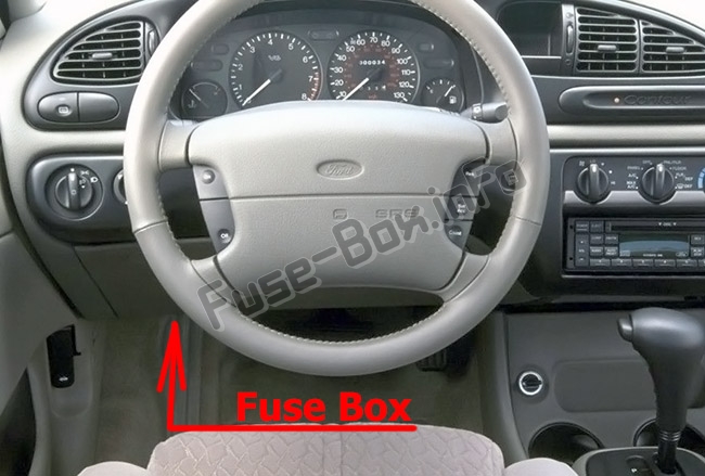
Fuse box diagram
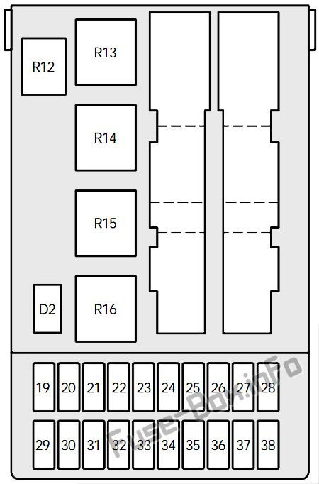
Assignment of the fuses and relays in the Passenger Compartment
| № | Amp Rating | Description |
|---|---|---|
| 19 | 7.5 | 1996-1997: Heated rear view mirrors 1998-2000: Not used |
| 20 | 10A | Wiper motors (circuit breaker) |
| 21 | 40 | Power windows |
| 22 | 7.5 | ABS module |
| 23 | 15 | Backup lamps |
| 24 | 15 | Brake lamps |
| 25 | 20 | Door locks |
| 26 | 7.5 | Main light |
| 27 | 15 | Cigar lighter |
| 28 | 30 | Electric seats |
| 29 | 30 | Rear window defrost |
| 30 | 7.5 | Engine management system |
| 31 | 7.5 | Instrument panel illumination |
| 32 | 7.5 | Radio |
| 33 | 7.5 | Left-hand parking lamps |
| 34 | 7.5 | 1996-1997: Courtesy lamps 1998-2000: Interior lighting/electric mirror adjustment/clock |
| 35 | 7.5 | Right-hand parking lamps |
| 36 | 10 | 1996-1998: Air bag 1999-2000: Not used |
| 37 | 30 | Heater blower motor |
| 38 | – | (not used) |
| Relays | ||
| R12 | white | 1996-1997: Courtesy lights 1998-2000: Interior lighting |
| R13 | yellow | Rear window defroster |
| R14 | yellow | Heater fan motor |
| R15 | green | Wipers |
| R16 | black | Ignition |
| D2 | black | Reverse voltage protection |
Engine Compartment Fuse Box
Engine Compartment Fuse Box
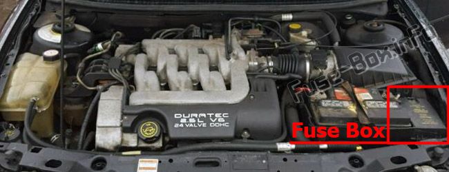
Fuse box location
Fuse box diagram (1996-1998)
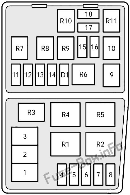
Assignment of the fuses and relays in the Engine Compartment (1996-1998)
| № | Amp Rating | Description |
|---|---|---|
| 1 | 80 | Main power supply to vehicle electrical system |
| 2 | 60 | Engine cooling fan |
| 3 | 60 | 1996-1997: ABS braking system 1998: ABS braking system, heater blower |
| 4 | 20 | 1996-1997: Daytime running lights (Canada) Ignition 1998: |
| 5 | 15 | Fog lamp |
| 6 | – | Not used |
| 7 | 30 | ABS braking system |
| 8 | 30 | 1996-1997: Air pump 1998: Not used |
| 9 | 20 | Electronic Engine Control (EEC) |
| 10 | 20 | Ignition switch |
| 11 | 3 | EEC ignition module (memory) |
| 12 | 15 | Hazard flashers Horn |
| 13 | 15 | HEGO sensor |
| 14 | 15 | Fuel pump |
| 15 | 10 | Right low beam |
| 16 | 10 | Left low beam |
| 17 | 10 | Right high beam |
| 18 | 10 | Left high beam |
| Relays | ||
| R1 | white | Daytime running lights (Canada) |
| R2 | black | High speed engine cooling fan |
| R3 | blue | A/C wide open throttle |
| R4 | yellow | A/C clutch relay |
| R5 | dark green | Engine cooling fan (low speed) |
| R6 | yellow | Starter |
| R7 | brown | Horn |
| R8 | brown | Fuel pump |
| R9 | white | Low beam headlamps |
| R10 | white | High beam headlamps |
| R11 | brown | 1996-1997: PCM module 1998: EEC module |
| D1 | black | Reverse voltage protection |
Fuse box diagram (1999-2000)
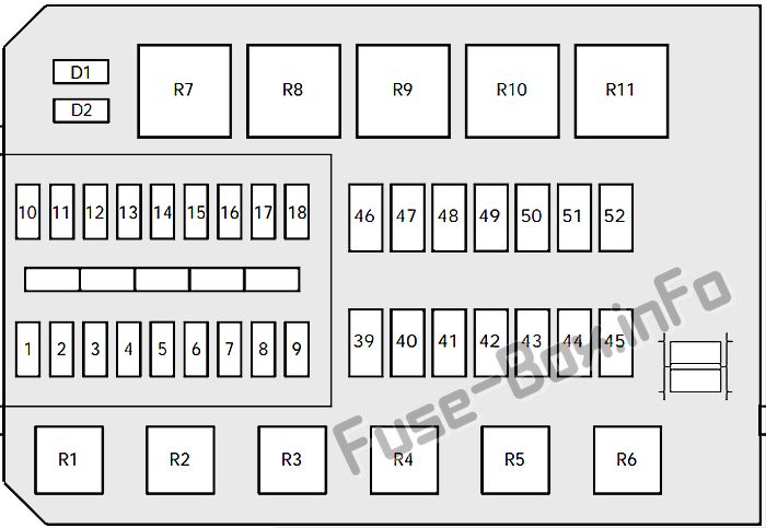
Assignment of the fuses and relays in the Engine Compartment (1999-2000)
| № | Ampere rating | Circuits protected |
|---|---|---|
| 1 | — | Not used |
| 2 | 7.5 | Alternator |
| 3 | 20 | Foglamps |
| 4 | — | Not used |
| 5 | — | Not used |
| 6 | 3 | EEC ignition module (memory) |
| 7 | 20 | Horn and hazard flasher warning system |
| 8 | — | Not used |
| 9 | 15 | Fuel pump |
| 10 | — | Not used |
| 11 | 20 | Ignition. Electronic Engine Control |
| 12 | — | Not used |
| 13 | 20 | HEGO sensor |
| 14 | 7.5 | ABS module |
| 15 | 7.5 | Low beam headlamp (passengers side) |
| 16 | 7.5 | Low beam headlamp (driver’s side) |
| 17 | 7.5 | High beam headlamp (passenger’s side) |
| 18 | 7.5 | High beam headlamp (driver’s side) |
| 39 | — | Not used |
| 40 | 20 | Ignition, light switch, central junction box |
| 41 | 20 | EEC relay |
| 42 | 40 | Central junction box (fuse 37 to blower relay) |
| 43 | — | Not used |
| 44 | — | Not used |
| 45 | 60 | Ignition |
| 46 | — | Not used |
| 47 | — | Not used |
| 48 | — | Not used |
| 49 | 60 | Engine cooling |
| 50 | — | not used |
| 51 | 60 | ABS |
| 52 | 60 | Central junction box (central timer module, rear window defrost relay, fuses 24, 25, 27, 28, 34) |
| Relays | ||
| R1 | Fuel pump | |
| R2 | EEC module | |
| R3 | Air conditioning | |
| R4 | Low beam | |
| R5 | High beam | |
| R6 | Horn | |
| R7 | Starter solenoid | |
| R8 | Engine cooling fan (high speed) | |
| R9 | Engine cooling fan | |
| R10 | Not used | |
| R11 | Daytime running lights | |
| D1 | Reverse voltage protection | |
| D2 | Not used |
Auxiliary relays (outside of fuseboxes)
Auxiliary relays (outside of fuseboxes)
| Relay | Description | Location |
|---|---|---|
| R17 | ||
| R18 | “One touch” switch (driver’s window) | Driver’s door |
| R19 | Speed control cut-out (1996-1997) | |
| R20 | ||
| R21 | ||
| R22 | Fog lamps | Wire shield on instrument panel |
| R23 | Turn signal | Steering column |
| R24 | Left panic alarm flasher | Door lock module bracket |
| R25 | Right panic alarm flasher | Door lock module bracket |
| R26 | ||
| R27 | ||
| R28 | ||
| R29 | Door lock control | |
| R32 | Hego heater control (2000) | Near PCM-Module |


