

Fuse Layout Volvo S40 2004-2012
Contents
Table of Contents
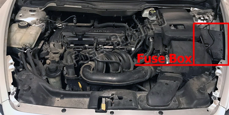
Fuse box location
Fuse box location
Engine compartment
Fuses for the Start/Stop function
Passenger compartment
The fuse box is located under the glove compartment.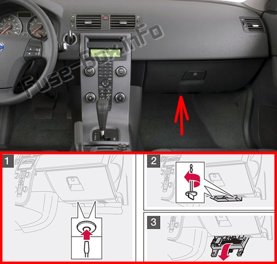
Fuse box diagrams
Fuse box diagrams
2007
Engine compartment
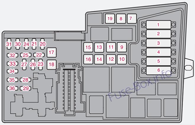
Assignment of fuses in the engine compartment (2007)
| № | Description | Amp |
|---|---|---|
| 1. | Coolant fan (radiator) | 50A |
| 2. | Power steering | 80A |
| 3. | Feed to passenger compartment fuse box | 60A |
| 4. | Feed to passenger compartment fuse box | 60A |
| 5. | Element, climate unit | 80A |
| 6. | Not in use | |
| 7. | ABS pump | 30A |
| 8 . | ABS valves | 20A |
| 9. | Engine functions | 30A |
| 10 . | Climate system blower | 40A |
| 11. | Headlight washers | 20A |
| 12. | Feed to heated rear window | 30A |
| 13. | Starter motor relay | 30A |
| 14. | Trailer connector | 40A |
| 15. | Not in use | |
| 16. | Feed to audio system | 30A |
| 17. | Windshield wipers | 30A |
| 18. | Feed to passenger compartment fuse box | 40A |
| 19. | Not in use | |
| 20. | Horn | 15A |
| 21. | Not in use | |
| 22. | Not in use | |
| 23. | Engine control module (ECM)/ transmission control module (TCM) | 10A |
| 24. | Not in use | |
| 25. | Not in use | |
| 26. | Ignition switch | 15A |
| 27. | A/C compressor, water shutoff valve | 10A |
| 28. | Not in use | |
| 29. | Front fog lights (option) | 15A |
| 30. | Not in use | |
| 31. | Not in use | |
| 32. | Fuel injectors | 10A |
| 33. | Heated oxygen sensor, vacuum pump | 20A |
| 34. | Ignition coils, climate unit pressure sensor | 10A |
| 35. | Engine sensor valves, A/C relay, relay coil water shut-off valve | 15A |
| 36. | Engine control module (ECM), throttle sensor | 10A |
Passenger compartment
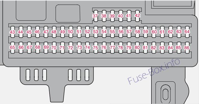
Assignment of fuses in the passenger compartment (2007)
| № | Description | Amp |
|---|---|---|
| 37. | Not in use | |
| 38. | Not in use | |
| 39. | Not in use | |
| 40. | Not in use | |
| 41. | Not in use | |
| 42. | Not in use | |
| 43. | Audio system, Volvo Navigation system (option) | 15A |
| 44. | Supplemental Restrain System (SR S) | 10A |
| 45. | 12-volt socket in rear seat | 15A |
| 46. | Lighting – glove compartment, instrument panel, and foot-wells | 5A |
| 47. | Interior lighting | 5A |
| 48. | Not in use | |
| 49. | Supplemental Restrain System (SRS), Occupant Weight Sensor (OWS) | 10A |
| 50. | Not in use | |
| 51. | Park assist (option), AWD, Bi-Xenon headlights (option) | 10A |
| 52. | Transmission control module (TCM), ABS | 5A |
| 53. | Power steering | 10A |
| 54. | Engine control module (ECM) | 10A |
| 55. | Not in use | |
| 56. | Alarm siren control module | 10A |
| 57. | On-board diagnostic socket, brake light switch | 15A |
| 58. | Right high beam, auxiliary lights relay | 7.5A |
| 59. | Left high beam | 7.5 |
| 60. | Heated driver’s seat (option) | 15A |
| 61. | Heated passenger’s seat (option) | 15A |
| 62. | Moonroof (option) | 20A |
| 63. | Power window’ and door lock -rear passenger’s side door | 20A |
| 64. | Audio system. Volvo Navigation system (option) | 5A |
| 65. | Audio system | 5A |
| 66. | Audio system control module (ICM), climate system | 10A |
| 67. | Not in use | |
| 68. | Cruise control | 5A |
| 69. | Climate system, rain sensor (option) | 5A |
| 70. | Not in use | |
| 71. | Not in use | |
| 72. | Not in use | |
| 73. | Moonroof, front ceiling lighting, auto-dim mirror, (option) seat belt reminder | 5A |
| 74. | Fuel pump relay | 15A |
| 75. | Not in use | |
| 76. | Not in use | |
| 77. | 12-voft socket in trunk, auxiliary equipment control module (AEM) | 15A |
| 78. | Not in use | |
| 79. | Back-up lights | 5A |
| 80. | Not in use | |
| 81. | Power window and door lock -rear driver’s side door | 20A |
| 82. | Power window and door lock -front passenger’s side door | 25A |
| 83. | Power window and door lock -front driver’s side door | 25A |
| 84. | Power passenger’s seat | 25A |
| 85. | Power driver’s seat | 25A |
| 86. | Interior lighting relay, trunk light, power seats | 5A |
2008
Engine compartment
Assignment of fuses in the engine compartment (2008)
| № | Description | Amp |
|---|---|---|
| 1. | Radiator fan | 50 A |
| 2. | Power steering. | 80 A |
| 3. | Supply to passenger compartment fuse box | 60 A |
| 4. | Supply to passenger compartment fuse box | 60 A |
| 5. | Climate control element, additional heater PTC (option) | 80 A |
| 6. | Glow plugs (4-cyl. diesel). | 60 A |
| 6. | Glow plugs (5-cyl. diesel). | 70 A |
| 7. | ABS pump. | 30 A |
| 8. | ABS valves | 20 A |
| 9. | Engine functions | 30 A |
| 10. | Ventilation fan. | 40 A |
| 11. | Headlamp washers | 20 A |
| 12. | Supply to heated rear window. | 30 A |
| 13. | Starter motor relay. | 30 A |
| 14. | Trailer wiring | 40 A |
| 15. | Reserve | – |
| 16. | Supply to infotainment system. | 30 A |
| 17. | Windscreen wipers. | 30 A |
| 18. | Supply to passenger compartment fuse box | 40 A |
| 19. | Reserve | – |
| 20. | Horn | 15 A |
| 21. | Fuel-driven additional heater, passenger compartment heater. | 20 A |
| 22 . | Reserve | – |
| 23. | Engine control module ECM (5-cyl. petrol), transmission (TCM) | 10 A |
| 24. | Heated fuel filter, PTC element oil trap (5-cyl. diesel) | 20 A |
| 25. | Reserve | – |
| 26. | Ignition switch | 15 A |
| 27. | A/C compressor | 10 A |
| 28. | Reserve | – |
| 29. | Front fog lamp | 15 A |
| 30. | Engine control module ECM (1.6 I petrol, 2.0 I diesel) | 3 A |
| 31. | Voltage regulator, alternator 4-cyl. | 10 A |
| 32. | Injectors (5-cyl. petrol), lambda-sond (4-cyl. petrol), charge air cooler (4-cyl. diesel), mass air flow sensor and turbo control (5-cyl. diesel) | 10 A |
| 33. | Lambda-sond and vacuum pump (5-cyl. petrol), engine control module (5-cyl. diesel), diesel filter heater (4-cyl. diesel). | 20 A |
| 34. | Ignition coils (petrol), injectors (1.6 l petrol), fuel pump (4-cyl. diesel), pressure switch, climate control (5-cyl.), glow plugs and EGR emission control (5-cyl. diesel) | 10 A |
| 35. | Engine sensors for valves, relay coil, air conditioning PTC element, oil trap (5-cyl. petrol), engine control module ECM (5-cyl. diesel), canister (petrol), injectors (1.8/2.0 l petrol), MAF mass air flow sensor (5-cyl. petrol, 4-cyl. diesel), turbo control (4-cyl. diesel), pressure switch power steering (1.6 l petrol), EGR emission control (4-cyl. diesel) | 15 A |
| 36. | Engine control module ECM (not 5-cyl. diesel), accelerator pedal position sensor, lambda-sond (5-cyl. diesel) | 10 A |
Passenger compartment
Assignment of fuses in the passenger compartment (2008)
| № | Description | Amp |
|---|---|---|
| 37. | Reserve | – |
| 38. | Reserve | – |
| 39. | Reserve | – |
| 40. | Reserve | – |
| 41. | Reserve | – |
| 42. | Reserve | – |
| 43. | Phone, audio system, RTI (option) | 15A |
| 44. | SRS system, engine control module ECM (5-cyl.) | 10A |
| 45. | Electrical socket | 15A |
| 46. | Passenger compartment, glovebox and courtesy lighting | 5A |
| 47. | Interior lighting | 5A |
| 48. | Washer | 15A |
| 49. | SRS system | 10A |
| 50. | Reserve | – |
| 51. | Additional heater for the passenger compartment, AWD, fuel filter relay, heating | 10A |
| 52. | Transmission control module (TCM), ABS system | 5A |
| 53. | Power steering | 10A |
| 54. | Parking assistance, Bi-Xenon (option) | 10A |
| 55. | Keyless control module | 20A |
| 56. | Remote control module, siren control module | 10A |
| 57. | Data link connector (DLC), brake light switch | 15A |
| 58. | Main beam (right), auxiliary lamps relay coil | 7,5A |
| 59. | Main beam, left | 7,5A |
| 60. | Seat heating (driver’s side) | 15A |
| 61. | Seat heating (passenger side) | 15A |
| 62. | Sunroof | 20A |
| 63. | Supply to rear right door | 20A |
| 64. | RTI (option) | 5A |
| 65. | Infotainment system | 5A |
| 66. | Infotainment control module (ICM), climate control | 10A |
| 67. | Reserve | – |
| 68. | Cruise control | 5A |
| 69. | Climate control, rain sensor, BLIS button | 5A |
| 70. | Reserve | – |
| 71. | Reserve | – |
| 72. | Reserve | – |
| 73. | Sunroof, overhead console for interior lighting (OHC), rear seatbelt reminder, autodim mirror | 5A |
| 74. | Fuel pump relay | 15A |
| 75. | Reserve | – |
| 76. | Reserve | – |
| 77. | Electrical socket in cargo area, accessory electronic module (AEM) | 15A |
| 78. | Reserve | – |
| 79. | Reversing lamp | 5A |
| 80. | Reserve | – |
| 81. | Supply to rear left door | 20A |
| 82. | Supply to front right door | 25A |
| 83. | Supply to front left door | 25A |
| 84. | Power passenger seat | 25A |
| 85. | Power driver’s seat | 25A |
| 86. | Interior lighting, cargo area lighting, power seats, fuel level display (1.8F) | 5A |
2009, 2010
Engine compartment
Assignment of fuses in the engine compartment (2009, 2010)
| № | Description | Amp |
|---|---|---|
| 1. | Coolant fan (radiator) | 50A |
| 2. | Power steering | 80A |
| 3. | Feed to passenger compartment fuse box | 60A |
| 4. | Feed to passenger compartment fuse box | 60A |
| 5. | Element, climate unit | 80A |
| 6. | Not in use | |
| 7. | ABS pump | 30A |
| 8. | ABS valves | 20A |
| 9. | Engine functions | 30A |
| 10. | Climate system blower | 40A |
| 11. | Headlight washers | 20A |
| 12. | Feed to heated rear window | 30A |
| 13. | Starter motor relay | 30A |
| 14. | Trailer connector (accessory) | 40A |
| 15. | Not in use | |
| 16. | Feed to audio system | 30A |
| 17 . | Windshield wipers | 30A |
| 18 . | Feed to passenger compartment fuse box | 40A |
| 19 . | Not in use | |
| 20. | Horn | 15A |
| 21. | Not in use | |
| 22. | Not in use | |
| 23. | Engine control module (ECM)/transmission control module (TCM) | 10A |
| 24. | Not in use | |
| 25. | Not in use | |
| 26. | Ignition switch | 15A |
| 27. | A/C compressor | 10A |
| 28. | Not in use | |
| 29. | Front fog lights (Option) | 15A |
| 30. | Not in use | |
| 31. | Not in use | |
| 32. | Fuel injectors | 10A |
| 33. | Heated oxygen sensor, vacuum pump | 20A |
| 34. | Ignition coils, climate unit pressure sensor | 10A |
| 35. | Engine sensor valves, A/C relay, relay coil, PTC element oil trap, canister, mass air meter | 15A |
| 36. | Engine control module (ECM), throttle sensor | 10A |
Passenger compartment
Assignment of fuses in the passenger compartment (2009, 2010)
| № | Description | Amp |
|---|---|---|
| – | Fuse 37-42, not in use | – |
| 43. | Audio system, Bluetooth,Volvo Navigation system (Option) | 15A |
| 44. | Supplemental Restrain System (SRS), engine control module | 10A |
| 45. | 12-volt socket in rear seat | 15A |
| 46. | Lighting – glove compartment, instrument panel, and footwells | 5A |
| 47. | Interior lighting | 5A |
| 48. | Windshield washers | 15A |
| 49. | Supplemental Restrain System (SRS), Occupant Weight Sensor (OWS) | 10A |
| 50. | Not in use | |
| 51. | AWD, fuel filter relay | 10A |
| 52. | Transmission control module (TCM), ABS | 5A |
| 53. | Power steering | 10A |
| 54. | Park assist (Option), Active Bending Lights (Option) | 10A |
| 55. | Not in use | |
| 56. | Volvo Navigation System remote key module, alarm siren control module | 10A |
| 57. | On-board diagnostic socket, brake light switch | 15A |
| 58. | Right high beam, auxiliary lights relay | 7.5A |
| 59. | Left high beam | 7.5A |
| 60. | Heated driver’s seat (Option) | 15A |
| 61. | Heated passenger’s seat (Option) | 15A |
| 62. | Moonroof (Option) | 20A |
| 63. | Power window and door lock – rear passenger’s side door | 20A |
| 64. | Audio system, Volvo Navigation system (Option) | 5A |
| 65. | Audio system | 5A |
| 66. | Audio system control module (ICM), climate system | 10A |
| 67. | Not in use | |
| 68. | Cruise control | 5A |
| 69. | Climate system, rain sensor (Option), BUS button (Option) | 5A |
| 70. | Not in use | |
| 71. | Not in use | |
| 72. | Not in use | |
| 73. | Moonroof, front ceiling lighting, auto-dim mirror (Option), seat belt reminder | 5A |
| 74. | Fuel pump relay | 15A |
| 75. | Not in use | |
| 76. | Not in use | |
| 77. | Auxiliary equipment control module (AEM) | 15A |
| 78. | Not in use | |
| 79. | Back-up lights | 5A |
| 80. | Not in use | |
| 81. | Power window and door lock – rear driver’s side door | 20A |
| 82. | Power window – front passenger’s side door | 25A |
| 83. | Power window and door lock – front driver’s side door | 25A |
| 84. | Power passenger’s seat | 25A |
| 85. | Power driver’s seat | 25A |
| 86. | Interior lighting relay, trunk lighting, power seats | 5A |
2011
Engine compartment
Assignment of fuses in the engine compartment (2011)
| № | Description | Amp |
|---|---|---|
| 1. | Coolant fan (radiator) | 50A |
| 2. | Power steering | 80A |
| 3. | Feed to passenger compartment fuse box | 60A |
| 4. | Feed to passenger compartment fuse box | 60A |
| 5. | Element, climate unit | 80A |
| 6. | Not in use | |
| 7. | ABS pump | 30A |
| 8. | ABS valves | 20A |
| 9. | Engine functions | 30A |
| 10. | Climate system blower | 40A |
| 11. | Headlight washers | 20A |
| 12. | Feed to heated rear window | 30A |
| 13. | Starter motor relay | 30A |
| 14. | Trailer connector (accessory) | 40A |
| 15. | Not in use | |
| 16. | Feed to audio system | 30A |
| 17. | Windshield wipers | 30A |
| 18. | Feed to passenger compartment fuse box | 40A |
| 19. | Not in use | |
| 20. | Horn | 15A |
| 21. | Not in use | |
| 22. | Not in use | |
| 23. | Engine control module (ECM)/transmission control module (TCM) | 10A |
| 24. | Not in use | |
| 25. | Not in use | |
| 26. | Ignition switch | 15A |
| 27. | A/C compressor | 10A |
| 28. | Not in use | |
| 29. | Front fog lights (Option) | 15A |
| 30. | Not in use | |
| 31. | Not in use | |
| 32. | Fuel injectors | 10A |
| 33. | Heated oxygen sensor, vacuum pump | 20A |
| 34. | Ignition coils, climate unit pressure sensor | 10A |
| 35. | Engine sensor valves, A/C relay, relay coil, PTC element oil trap, canister, mass air meter | 15A |
| 36. | Engine control module (ECM), throttle sensor | 10A |
Passenger compartment
Assignment of fuses in the passenger compartment (2011)
| № | Description | Amp |
|---|---|---|
| – | Fuse 37-42, not in use | – |
| 43. | Audio system, Bluetooth,Volvo Navigation system (Option) | 15A |
| 44. | Supplemental Restrain System (SRS), engine control module | 10A |
| 45. | 12-volt socket in rear seat | 15A |
| 46. | Lighting – glove compartment, instrument panel, and footwells | 5A |
| 47. | Interior lighting | 5A |
| 48. | Windshield washers | 15A |
| 49. | Supplemental Restrain System (SRS), Occupant Weight Sensor (OWS) | 10A |
| 50. | Not in use | |
| 51. | AWD, fuel filter relay | 10A |
| 52. | Transmission control module (TCM), ABS | 5A |
| 53. | Power steering | 10A |
| 54. | Park assist (Option), Active Bending Lights (Option) | 10A |
| 55. | Not in use | |
| 56. | Volvo Navigation System remote key module, alarm siren control module | 10A |
| 57. | On-board diagnostic socket, brake light switch | 15A |
| 58. | Right high beam, auxiliary lights relay | 7.5A |
| 59. | Left high beam | 7.5A |
| 60. | Heated driver’s seat (Option) | 15A |
| 61. | Heated passenger’s seat (Option) | 15A |
| 62. | Moonroof (Option) | 20A |
| 63. | Power window and door lock – rear passenger’s side door | 20A |
| 64. | Sirius satellite radio (Option) | 5A |
| 65. | Audio system | 5A |
| 66. | Audio system control module (ICM), climate system | 10A |
| 67. | Not in use | |
| 68. | Cruise control | 5A |
| 69. | Climate system, rain sensor (Option), BUS button (Option) | 5A |
| 70. | Not in use | |
| 71. | Not in use | |
| 72. | Not in use | |
| 73. | Moonroof, front ceiling lighting, auto-dim mirror (Option), seat belt reminder | 5A |
| 74. | Fuel pump relay | 15A |
| 75. | Not in use | |
| 76. | Not in use | |
| 77. | Auxiliary equipment control module (AEM) | 15A |
| 78. | Not in use | |
| 79. | Back-up lights | 5A |
| 80. | Not in use | |
| 81. | Power window and door lock – rear driver’s side door | 20A |
| 82. | Power window – front passenger’s side door | 25A |
| 83. | Power window and door lock – front driver’s side door | 25A |
| 84. | Power passenger’s seat | 25A |
| 85. | Power driver’s seat | 25A |
| 86. | Interior lighting relay, trunk lighting, power seats | 5A |
2012
Engine compartment
Assignment of fuses in the engine compartment (2012)
| № | Description | Amp |
|---|---|---|
| 1. | Cooling fan | 50 A |
| 2. | Power steering | 80 A |
| 3. | Supply to passenger compartment fuse box | 60 A |
| 4. | Supply to passenger compartment fuse box | 60 A |
| 5. | PTC element, air preheater (Option) | 80 A |
| 6. | Glow plugs (DRIVe) | 60 A |
| 6. | Glow plugs (5-cyl. diesel) | 70 A |
| 7. | ABS pump | 40 A |
| 8. | ABS valves | 20 A |
| 9. | Engine functions | 30 A |
| 10. | Ventilation fan | 40 A |
| 11. | Headlamp washers | 20 A |
| 12. | Heated rear window | 30 A |
| 13. | Actuator solenoid, starter motor | 30 A |
| 14. | Trailer wiring (Option) | 40 A |
| 15. | Reserve | – |
| 16. | Infotainment system | 30 A |
| 17. | Windscreen wipers | 30 A |
| 18. | Supply to passenger compartment fuse box | 40 A |
| 19. | Reserve | – |
| 20. | Horn | 15 A |
| 21. | Fuel-driven additional heater, passenger compartment heater (Option) | 20 A |
| 22. | Reserve | – |
| 23. | Engine control module (5-cyl. petrol), Transmission control module (5-cyl.) | 10 A |
| 23. | Transmission control module (4-cyl.) | 15 A |
| 24. | Heated fuel filter (5-cyl. diesel), PTC element, oil trap (5-cyl. diesel) | 20 A |
| 25. | Central electronic module (CEM) (Start/Stop) | 10 A |
| 26. | Ignition switch | 15 A |
| 27. | A/C compressor | 10 A |
| 28. | Reserve | – |
| 29. | Front fog lamps Daytime running lights (DRL) (Option) | 15 A |
| 30. | Coolant pump (Start/Stop) | 10 A |
| 31. | Voltage regulator, alternator (4-cyl. petrol) | 10 A |
| 32. | Injectors (5-cyl. petrol), Turbo control valve (5-cyl. diesel), Oil level sensor (5-cyl. diesel) Control valve, fuel flow (DRIVe), Mass air flow sensor (DRIVe), Control motor turbo (DRIVe) | 10 A |
| 33. | Vacuum pump (5-cyl. petrol), Relay coil, relay, vacuum pump (5-cyl. petrol), Engine control module (5-cyl. diesel), Heated fuel filter (DRIVe) | 20 A |
| 34. | Ignition coils (petrol), Pressure switch, climate control system (5-cyl.), Control module, glow plugs (5-cyl. diesel), EGR emission control (5-cyl. diesel), Fuel pump (DRIVe), Lambda-sond (DRIVe), Engine control module (Start/Stop), Relay coils, relays Start/Stop | 10 A |
| 35. | Relay coil, relay, climate control system, PTC element, oil trap (5-cyl. petrol), Mass air flow sensor (5-cyl. petrol), Turbo control valve (5-cyl. petrol), Solenoids, variable valve timing (5-cyl. petrol), Injectors (2.0 l petrol), EVAP valve (2.0 l petrol), Valve, air/fuel mixture (2.0 l petrol), Control valve, fuel pressure (5-cyl. diesel), Engine control module (5-cyl. diesel), Engine EGR (DRIVe) | 15 A |
| 36. | Engine control module (petrol, DRIVe), Accelerator pedal position sensor (5-cyl. diesel), Lambda-sond (5-cyl. diesel) | 10 A |
Passenger compartment
Assignment of fuses in the passenger compartment (2012)
| № | Description | Amp |
|---|---|---|
| 43. | Telematics (Option), Audio system, RTI (Option), Bluetooth (Option) | 15 A |
| 44. | SRS system, Engine control module (5-cyl, DRIVe) | 10 A |
| 45. | Electrical socket, passenger compartment | 15 A |
| 46. | Passenger compartment, glo-vebox and courtesy lighting | 5 A |
| 47. | Interior lighting, Remote controlled garage door opener (Option) | 5 A |
| 48. | Washer | 15 A |
| 49. | SRS system | 10 A |
| 50. | Reserve | – |
| 51. | PTC element, air preheater (Option), Relay coil, relay, heated fuel filter (5-cyl. diesel), AWD | 10 A |
| 52. | Transmission control module, ABS system | 5 A |
| 53. | Power steering | 10 A |
| 54. | Parking assistance (Option), Xenon (Option) | 10 A |
| 55. | Control module Keyless (Option) | 20 A |
| 56. | Remote control receiver, Siren (Option) | 10 A |
| 57. | Data link connector (DLC), brake light switch | 15 A |
| 58. | Main beam, right, Relay coil, relay, auxiliary lamps (Option) | 7.5 A |
| 59. | Main beam, left | 7.5 A |
| 60. | Seat heating (driver’s side) | 15 A |
| 61. | Seat heating (passenger side) | 15 A |
| 62. | Sunroof (Option) | 20 A |
| 63. | Supply to rear right door | 20 A |
| 64. | Reserve | – |
| 65. | Audio, Infotainment | 5 A |
| 66. | Audio, Infotainment, Climate control system | 10 A |
| 67. | Reserve | – |
| 68. | Cruise control | 5 A |
| 69. | Climate control system, Rain sensor, Buttons for BUS (Option), parking assistance (Option), DRIVe | 5 A |
| 70. | Reserve | – |
| 71. | Reserve | – |
| 72. | Reserve | – |
| 73. | Sunroof (Option), Overhead console for interior lighting, Seatbelt reminder, rear, Dimming, interior rearview mirror (Option) | 5 A |
| 74. | Fuel pump | 15 A |
| 75. | Reserve | – |
| 76. | Reserve | – |
| 77. | Electrical socket cargo area, Control module, accessories (Option) | 15 A |
| 78. | Reserve | – |
| 79. | Reversing lamp, Dimming, interior rearview mirror (signal) | 5 A |
| 80. | Reserve | – |
| 81. | Supply to rear left door | 20 A |
| 82. | Supply to front right door | 25 A |
| 83. | Supply to front left door | 25 A |
| 84. | Power seat, passenger | 25 A |
| 85. | Power seat, driver | 25 A |
| 86. | Interior lighting, cargo area lighting, power seats, fuel level display (2.0F) | 5 A |
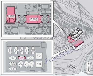
Fuses for the Start/Stop function
Fuses for the Start/Stop function
Location of fuses for the Start/Stop function
| № | Component | Amp |
|---|---|---|
| 11M/1 | Engine compartment, electrical distribution unit | 125 |
| 11M/2 | Sensor, battery monitoring | 15 |
| 25 | Central electronic module (CEM) (Reference voltage standby battery), diesel engine | 10 |


