

Fuse Layout Volvo C70 2006-2013
Contents
Cigar lighter (power outlet) fuse in the Volvo C70 is the fuse #45 (12-volt socket in passenger compartment) and #77 (12-volt socket in trunk) in the passenger compartment fuse box.
Table of Contents
Fuse box location
Fuse box location
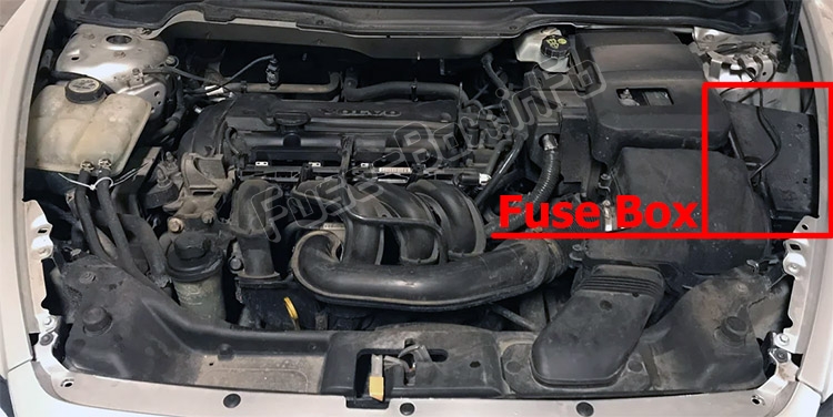
Engine compartment
Passenger compartment
The fuse box is located under the glove compartment.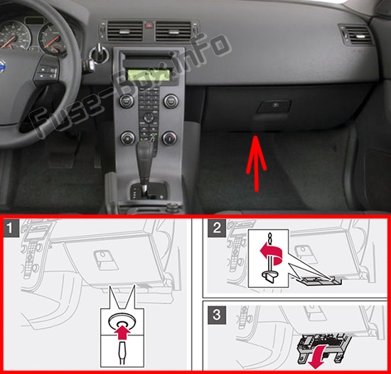
Fuse box diagrams
Fuse box diagrams
2008
Engine compartment
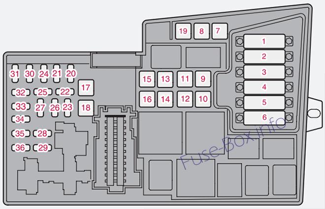
Assignment of fuses in the engine compartment (2008)
| № | Description | Amp |
|---|---|---|
| 1 | Coolant fan (radiator) | 50A |
| 2 | Power steering | 80A |
| 3 | Feed to passenger compartment fuse box | 60A |
| 4 | Feed to passenger compartment fuse box | 60A |
| 5 | Not in use | |
| 6 | Not in use | |
| 7 | ABS pump | 30A |
| 8 | ABS | 30A |
| 9 | Engine functions | 30A |
| 10 | Climate system blower | 40A |
| 11 | Headlight washers, power retractable hard top, locking storage compartments | 20A |
| 12 | Feed to heated rear window | 30A |
| 13 | Starter motor relay | 30A |
| 14 | Trailer connector | 40A |
| 15 | Power retractable hard top | 30A |
| 16 | Feed to audio system | 40A |
| 17 | Windshield wipers | 30A |
| 18 | Feed to passenger compartment fuse box | 40A |
| 19 | Not in use | |
| 20 | Horn | 10A |
| 21 | Not in use | |
| 22 | Subwoofer | 20A |
| 23 | Engine control module (ECM)/transmission control module (TCM) | 10A |
| 24 | Not in use | |
| 25 | Not in use | |
| 26 | Ignition switch | 10A |
| 27 | A/C compressor | 10A |
| 28 | Not in use | |
| 29 | Front fog lights (option) | 10A |
| 30 | Not in use | |
| 31 | Not in use | |
| 32 | Fuel injectors | 10A |
| 33 | Heated oxygen sensor, vacuum pump | 20A |
| 34 | Ignition coils, climate unit pressure sensor | 10A |
| 35 | Engine sensor valves, A/C relay, PTC element oil trap, charcoal filter, air mass sensor | 10A |
| 36 | Engine control module (ECM), throttle sensor | 10A |
Passenger compartment
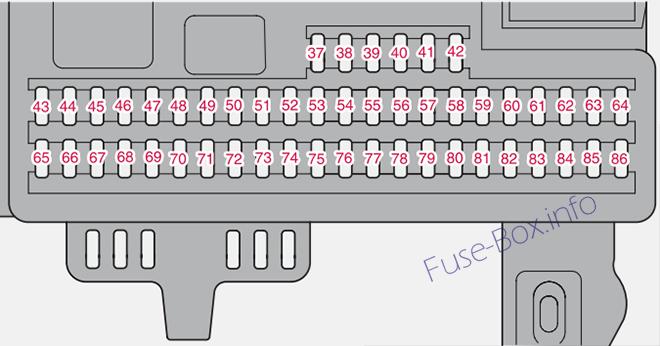
Assignment of fuses in the passenger compartment (2008)
| № | Description | Amp |
|---|---|---|
| 37 | Not in use | |
| 38 | Not in use | |
| 39 | Not in use | |
| 40 | Not in use | |
| 41 | Not in use | |
| 42 | Not in use | |
| 43 | Audio system, Volvo Navigation system (option) | 15A |
| 44 | Supplemental Restrain System (SRS), engine control module | 10A |
| 45 | 12-volt socket in passenger compartment | 15A |
| 46 | Lighting – glove compartment, instrument panel and footwells | 5A |
| 47 | Interior lighting | 5A |
| 48 | Windshield washers | 15A |
| 49 | Supplemental Restrain System (SRS), Occupant Weight Sensor (OWS) | 10A |
| 50 | Not in use | |
| 51 | Fuel filter relay | 10A |
| 52 | Transmission control module (TCM), ABS | 5A |
| 53 | Power steering | 10A |
| 54 | Park assist (option), Bi-Xenon® headlights (option) | 10A |
| 55 | Not in use | |
| 56 | Volvo Navigation System remote control (option), alarm siren control module | 10A |
| 57 | On-board diagnostic socket, brake light switch | 15A |
| 58 | Right high beam, auxiliary lights relay | 5A |
| 59 | Left high beam | 5A |
| 60 | Heated driver’s seat (option) | 15A |
| 61 | Heated passenger’s seat (option) | 15A |
| 62 | Not in use | |
| 63 | Power window rear passenger’s side | 20A |
| 64 | Lock indicator lights door panels, Volvo Navigation system(option) | 5A |
| 65 | Audio system 5A | 5A |
| 66 | Audio system control module (ICM), climate system | 10A |
| 67 | Not in use | |
| 68 | Cruise control | 5A |
| 69 | Climate system, rain sensor (option), BLIS button (option) | 5A |
| 70 | Not in use | |
| 71 | Not in use | |
| 72 | Not in use | |
| 73 | Front ceiling lighting | 5A |
| 74 | Fuel pump relay | 15A |
| 75 | Not in use | |
| 76 | Not in use | |
| 77 | 12-volt socket in trunk, auxiliary equipment control module (AEM) | 15A |
| 78 | Not in use | |
| 79 | Back-up lights | 5A |
| 80 | Not in use | |
| 81 | Power window – rear driver’s side | 20A |
| 82 | Power window and door lock – front passenger’s side door | 25A |
| 83 | Power window and door lock – front driver’s side door | 25A |
| 84 | Power passenger’s seat (option) | 25A |
| 85 | Power driver’s seat (option) | 25A |
| 86 | Interior lighting relay, trunk light, power seats | 5A |
2009, 2010
Engine compartment
Assignment of fuses in the engine compartment (2009, 2010)
| № | Description | Amp |
|---|---|---|
| 1. | Coolant fan (radiator) | 50A |
| 2. | Power steering | 80A |
| 3. | Feed to passenger compartment fuse box | 60A |
| 4. | Feed to passenger compartment fuse box | 60A |
| 5. | Element, climate unit | 80A |
| 6. | Not in use | |
| 7. | ABS pump | 30A |
| 8. | ABS valves | 20A |
| 9. | Engine functions | 30A |
| 10. | Climate system blower | 40A |
| 11. | Headlight washers, climate system blower, power retractable hard top, locking storage compartments | 20A |
| 12. | Feed to heated rear window | 30A |
| 13. | Starter motor relay | 30A |
| 14. | Trailer connector (accessory) | 40A |
| 15. | Power retractable hard top | 30A |
| 16. | Feed to audio system | 40A |
| 17. | Windshield wipers | 30A |
| 18. | Feed to passenger compartment fuse box | 40A |
| 19. | Not in use | |
| 20. | Horn | 15A |
| 21. | Not in use | |
| 22. | Subwoofer | 25A |
| 23. | Engine control module (ECM)/transmission control module (TCM) | 10A |
| 24. | Not in use | |
| 25. | Not in use | |
| 26. | Ignition switch | 15A |
| 27. | A/C compressor | 10A |
| 28. | Not in use | |
| 29. | Front fog lights (Option) | 15A |
| 30. | Not in use | |
| 31. | Not in use | |
| 32. | Fuel injectors | 10A |
| 33. | Heated oxygen sensor, vacuum pump | 20A |
| 34. | Ignition coils, climate unit pressure sensor | 10A |
| 35. | Engine sensor valves, A/C relay, relay coil, PTC element oil trap, canister, mass air meter | 15A |
| 36. | Engine control module (ECM), throttle sensor | 10A |
Passenger compartment
Assignment of fuses in the passenger compartment (2009, 2010)
| № | Description | Amp |
|---|---|---|
| – | Fuse 37-42, not in use | – |
| 43. | Audio system, Bluetooth,Volvo Navigation system (Option) | 15A |
| 44. | Supplemental Restrain System (SRS), engine control module | 10A |
| 45. | 12-volt socket in passenger’s compartment | 15A |
| 46. | Lighting – glove compartment, instrument panel, and footwells | 5A |
| 47. | Interior lighting | 5A |
| 48. | Windshield washers | 15A |
| 49. | Supplemental Restrain System (SRS), Occupant Weight Sensor (OWS) | 10A |
| 50. | Not in use | |
| 51. | Fuel filter relay | 10A |
| 52. | Transmission control module (TCM), ABS | 5A |
| 53. | Power steering | 10A |
| 54. | Park assist (Option), Dual Xenon headlights (Option) | 10A |
| 55. | Not in use | |
| 56. | Volvo Navigation System remote key module, alarm siren control module | 10A |
| 57. | On-board diagnostic socket, brake light switch | 15A |
| 58. | Right high beam, auxiliary lights relay | 7.5A |
| 59. | Left high beam | 7.5A |
| 60. | Heated driver’s seat (Option) | 15A |
| 61. | Heated passenger’s seat (Option) | 15A |
| 62. | Not in use | |
| 63. | Power window – rear passenger’s side | 20A |
| 64. | Volvo Navigation system (Option), lock indicator lights in door panels | 5A |
| 65. | Audio system | 5A |
| 66. | Audio system control module (ICM), climate system | 10A |
| 67. | Not in use | |
| 68. | Cruise control | 5A |
| 69. | Climate system, rain sensor (Option), BUS button (Option) | 5A |
| 70. | Not in use | |
| 71. | Not in use | |
| 72. | Not in use | |
| 73. | Front ceiling lighting | 5A |
| 74. | Fuel pump relay | 15A |
| 75. | Not in use | |
| 76. | Not in use | |
| 77. | 12-volt socket in trunk, auxiliary equipment control module (AEM) | 15A |
| 78. | Not in use | |
| 79. | Back-up lights | 5A |
| 80. | Not in use | |
| 81. | Power window and door lock – rear driver’s side | |
| 82. | Power window – front passenger’s side door | 25A |
| 83. | Power window and door lock – front driver’s side door | 25A |
| 84. | Power passenger’s seat | 25A |
| 85. | Power driver’s seat | 25A |
| 86. | Interior lighting relay, trunk lighting, power seats | 5A |
2011, 2012, 2013
Engine compartment
Assignment of fuses in the engine compartment (2011, 2012, 2013)
| № | Description | Amp |
|---|---|---|
| 1. | Coolant fan (radiator) | 50A |
| 2. | Power steering | 80A |
| 3. | Feed to passenger compartment fuse box | 60A |
| 4. | Feed to passenger compartment fuse box | 60A |
| 5. | Element, climate unit | 80A |
| 6. | Not in use | |
| 7. | ABS pump | 30A |
| 8. | ABS valves | 20A |
| 9. | Engine functions | 30A |
| 10. | Climate system blower | 40A |
| 11. | Headlight washers, climate system blower, power retractable hard top | 20A |
| 12. | Feed to heated rear window | 30A |
| 13. | Starter motor relay | 30A |
| 14. | Trailer connector (accessory) | 40A |
| 15. | Power retractable hard top | 30A |
| 16. | Feed to audio system | 40A |
| 17. | Windshield wipers | 30A |
| 18. | Feed to passenger compartment fuse box | 40A |
| 19. | Not in use | |
| 20. | Horn | 15A |
| 21. | Not in use | |
| 22. | Subwoofer | 25A |
| 23. | Engine control module (ECM)/transmission control module (TCM) | 10A |
| 24. | Not in use | |
| 25. | Not in use | |
| 26. | Ignition switch | 15A |
| 27. | A/C compressor | 10A |
| 28. | Not in use | |
| 29. | Front fog lights (Option) | 15A |
| 30. | Not in use | |
| 31. | Not in use | |
| 32. | Fuel injectors | 10A |
| 33. | Heated oxygen sensor, vacuum pump | 20A |
| 34. | Ignition coils, climate unit pressure sensor | 10A |
| 35. | Engine sensor valves, A/C relay, relay coil, PTC element oil trap, canister, mass air meter | 15A |
| 36. | Engine control module (ECM), throttle sensor | 10A |
Passenger compartment
Assignment of fuses in the passenger compartment (2011, 2012, 2013)
| № | Description | Amp |
|---|---|---|
| – | Fuse 37-42, not in use | – |
| 43. | Audio system, Bluetooth,Volvo Navigation system (Option) | 15A |
| 44. | Supplemental Restrain System (SRS), engine control module | 10A |
| 45. | 12-volt sockets in passenger’s compartment | 15A |
| 46. | Lighting – glove compartment, instrument panel, and footwells | 5A |
| 47. | Interior lighting | 5A |
| 48. | Windshield washers | 15A |
| 49. | Supplemental Restrain System (SRS), Occupant Weight Sensor (OWS) | 10A |
| 50. | Not in use | |
| 51. | Fuel filter relay | 10A |
| 52. | Transmission control module (TCM), ABS | 5A |
| 53. | Power steering | 10A |
| 54. | Park assist (Option), Active Bending Lights (Option) | 10A |
| 55. | Not in use | |
| 56. | Volvo Navigation System remote key module, alarm siren control module | 10A |
| 57. | On-board diagnostic socket, brake light switch | 15A |
| 58. | Right high beam, auxiliary lights relay | 7.5A |
| 59. | Left high beam | 7.5A |
| 60. | Heated driver’s seat (Option) | 15A |
| 61. | Heated passenger’s seat (Option) | 15A |
| 62. | Not in use | |
| 63. | Power window – rear passenger’s side | 20A |
| 64. | Sirius satellite radio (Option) | 5A |
| 65. | Audio system | 5A |
| 66. | Audio system control module (ICM), climate system | 10A |
| 67. | Not in use | |
| 68. | Cruise control | 5A |
| 69. | Climate system, rain sensor (Option), BUS button (Option) | 5A |
| 70. | Not in use | |
| 71. | Not in use | |
| 72. | Not in use | |
| 73. | Front ceiling lighting | 5A |
| 74. | Fuel pump relay | 15A |
| 75. | Not in use | |
| 76. | Not in use | |
| 77. | 12-volt socket in trunk, Auxiliary equipment control module (AEM) | 15A |
| 78. | Not in use | |
| 79. | Back-up lights | 5A |
| 80. | Not in use | |
| 81. | Power window – rear driver’s side | 20A |
| 82. | Power window – front passenger’s side door | 25A |
| 83. | Power window and door lock – front driver’s side door | 25A |
| 84. | Power passenger’s seat | 25A |
| 85. | Power driver’s seat | 25A |
| 86. | Interior lighting relay, trunk lighting, power seats | 5A |


