


Fuse Layout Toyota Verso-S / Ractis 2010-2017
Contents
Cigar lighter (power outlet) fuse in the Toyota Verso-S / Ractis is the fuse #23 “CIG” in the Instrument panel fuse box.
Table of Contents
Passenger Compartment Overview
Passenger Compartment Overview
Left-hand drive vehicles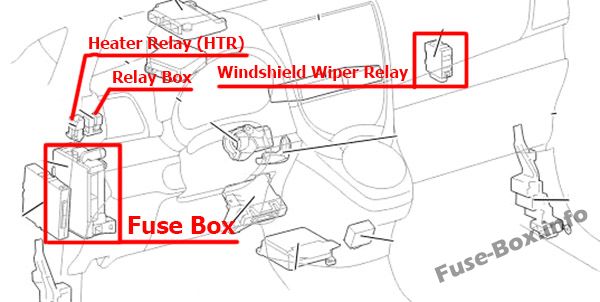
Right-hand drive vehicles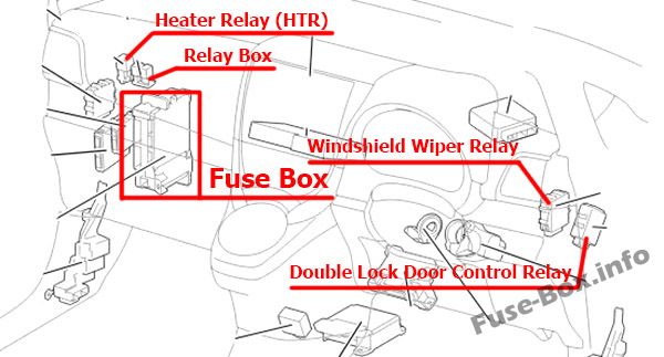
Passenger Compartment Fuse box
Fuse box location
The fuse box is located under the instrument panel (on the left-side), under the cover.
Left-hand drive vehicles: Open the lid.
Right-hand drive vehicles: Remove the cover and open the lid.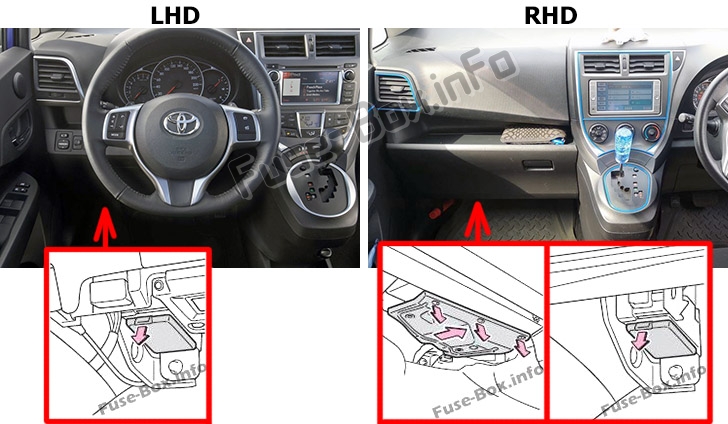
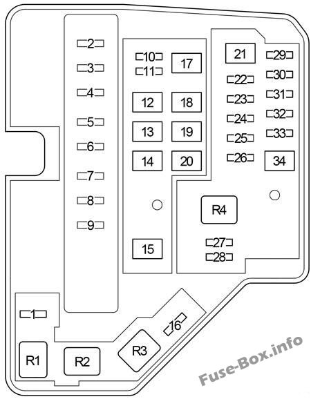
Fuse box diagram
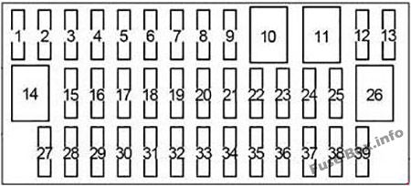
Assignment of the fuses in the Passenger Compartment
| № | Name | Amp | Circuit |
|---|---|---|---|
| 1 | – | – | – |
| 2 | – | – | – |
| 3 | – | – | – |
| 4 | S-HTR | 15 | Seat heaters |
| 5 | – | – | – |
| 6 | – | – | – |
| 7 | – | – | – |
| 8 | SHADE | 25 | Panoramic roof shade |
| 9 | – | – | – |
| 10 | – | – | – |
| 11 | – | – | – |
| 12 | D-D/L | 25 | Multiport fuel injection system/sequential multiport fuel injection system |
| 13 | – | – | – |
| 14 | – | – | – |
| 15 | FOG FR | 15 | Front fog lights, gauge and meters |
| 16 | AM1 | 7.5 | Starting system |
| 17 | STOP | 7.5 | Multiport fuel injection system/sequential multiport fuel injection system, smart entry & start system, ABS, VSC, multi-mode manual transmission, stop lights, high mounted stoplight, shift lock control system |
| 18 | FOG RR | 7.5 | Rear fog light, gauge and meters |
| 19 | – | – | – |
| 20 | OBD | 7.5 | On-board diagnosis system |
| 21 | D/L | 25 | Power door lock system |
| 22 | ACC | 5 | Main body ECU, outside rear view mirrors, audio system, Stop & Start system, shift lock control system |
| 23 | CIG | 15 | Power outlets |
| 24 | DOOR | 20 | Power windows |
| 25 | DOOR R/L | 20 | Power windows |
| 26 | P/W | 30 | Power windows |
| 27 | WIPER RR | 15 | Rear window wiper |
| 28 | WIPER | 20 | Windshield wipers |
| 29 | WASHER | 15 | Windshield washer |
| 30 | – | – | – |
| 31 | – | – | – |
| 32 | GAUGE | 10 | Back-up light, shift lock control system, rear seat belt reminder lights, auto antiglare inside rear view mirror, multidrive, audio system, panoramic roof shade, multiport fuel injection system/sequential multiport fuel injection system, rain sensor |
| 33 | A/C | 7.5 | Air conditioning system, power heater, rear window defogger, outside rear view mirror defoggers |
| 34 | ECU-IG NO.2 | 5 | ABS, VSC, Stop & Start system |
| 35 | ECU-IG NO.1 | 5 | Electric cooling fan, rear window defogger, electric power steering, main body ECU, windshield wipers, VSC |
| 36 | DOOR P | 20 | Power windows |
| 37 | DOOR R/R | 20 | Power windows |
| 38 | PANEL | 5 | Gauge and meters, instrument panel lights, switch illumination |
| 39 | TAIL NO.2 | 10 | Front position lights, tail lights, license plate lights, front fog lights, rear fog light, multiport fuel injection system/sequential multiport fuel injection system, gauge and meters |
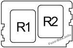
Relay Box
| № | Relay |
|---|---|
| R1 | – |
| R2 | Front fog light (FR FOG) |
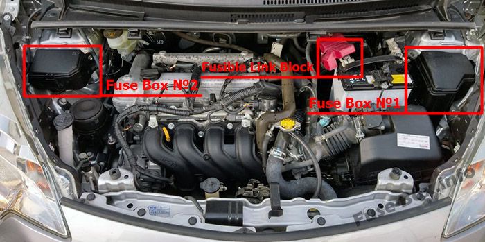
Engine Compartment Fuse Boxes
Engine Compartment Fuse Boxes
Fuse box location
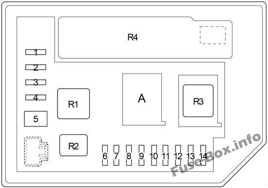
Fuse Box №1 Diagram
Assignment of the fuses and relay in the Engine Compartment Fuse Box №1
| № | Name | Amp | Circuit |
|---|---|---|---|
| 1 | ID/UP | 7.5 | Multiport fuel injection system/sequential multiport fuel injection system |
| 2 | EFI MAIN | 20 | Gasoline: Multiport fuel injection system/sequential multiport fuel injection system |
| 2 | ECD MAIN | 30 | Diesel: Multiport fuel injection system/sequential multiport fuel injection system, “EFI NO.2” fuse |
| 3 | EFI NO.3 | 7.5 | Multiport fuel injection system/sequential multiport fuel injection system |
| 4 | HORN | 10 | Horn |
| 5 | EFI NO.2 | 10 | Stop & Start system, multiport fuel injection system/sequential multiport fuel injection system |
| 6 | IG2 | 10 | Smart entry & start system, multiport fuel injection system/sequential multiport fuel injection system, multi-mode manual transmission, SRS airbag system, steering lock system, stop lights, Stop & Start system |
| 7 | IGN | 15 | Multiport fuel injection system/sequential multiport fuel injection system |
| 8 | MET | 7.5 | Gauge and meters, Stop & Start system |
| 9 | – | – | – |
| 10 | – | – | – |
| 11 | PWR HTR | 25 | Power heater, multiport fuel injection system/sequential multiport fuel injection system |
| 12 | EPS | 50 | Electric power steering |
| 13 | ABS NO.2 | 30 | ABS, VSC |
| 14 | DEF | 30 | Rear window defogger |
| 15 | PTC | 80 | PTC heater, outside rear view mirror defoggers |
| 16 | – | – | – |
| 17 | HTR | 40 | Air conditioning system |
| 18 | – | – | – |
| 19 | RDI FAN | 30 | Electric cooling fan |
| 20 | ABS NO.1 | 50 | ABS, VSC |
| 21 | BBC | 40 | Stop & Start system |
| 22 | ST | 30 | Starting system |
| 23 | – | – | – |
| 24 | D/L NO.2 | 25 | Power door lock |
| 25 | D.C.C | 30 | “DOME”, “ECU-B NO.1” fuses |
| 26 | STR LOCK | 20 | Steering lock system |
| 27 | ECU-B NO.1 | 5 | Main body ECU, smart entry 8t. start system |
| 28 | DOME | 15 | Interior lights, audio system, VSC |
| 29 | ETCS | 10 | Multiport fuel injection system/sequential multiport fuel injection system |
| 30 | HAZ | 10 | Turn signal lights |
| 31 | AM2 | 7.5 | Multiport fuel injection system/sequential multiport fuel injection system, smart entry & start system, starting system, multi-mode manual transmission |
| 32 | ECU-B NO.2 | 5 | Gauge and meters, power door lock, wireless remote control, Stop & Start system, smart entry & start system, multi-mode manual transmission, air conditioning system |
| 33 | – | – | – |
| 34 | R/I | 50 | “EFI MAIN”, “ECD MAIN”, “EFI NO.2”, “EFI NO.3”, “IG2”, “IGN”, “MET”, “HORN” fuses |
| Relay | |||
| R1 | Electric cooling fan (FAN NO.2) | ||
| R2 | Electric cooling fan (FAN NO.1) | ||
| R3 | Rear window defogger (DEF) | ||
| R4 | Starting system (ST) with Stop & Start System; 1NZ-FE: Starting system (ST2) |
Fuse Box №2 Diagram
A:
Type 1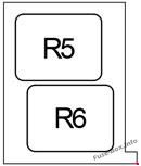
Type 2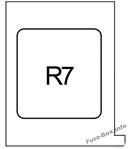
Engine Compartment Fuse Box №2
| № | Name | Amp | Circuit |
|---|---|---|---|
| 1 | – | – | – |
| 2 | EU-DRL | 15 | Headlight |
| 3 | S-HORN | 10 | Multiport fuel injection system/sequential multiport fuel injection system |
| 4 | H-LP MAIN | 7.5 | “H-LP RH LO”, “H-LP LH LO” fuses |
| 5 | MMT | 50 | Multi-mode manual transmission |
| 5 | ST | 40 | with Stop & Start System; 1NZ-FE: Starting system |
| 6 | H-LP RH HI | 10 | Right-hand headlight (high beam) |
| 7 | H-LP LH HI | 10 | Left-hand headlight (high beam), gauge and meters |
| 8 | H-LP RH LO | 10 | Halogen: Right-hand headlight (low beam) |
| 8 | H-LP RH LO | 15 | HID: Right-hand headlight (low beam) |
| 9 | H-LP LH LO | 10 | Halogen: Left-hand headlight (low beam), manual headlight leveling dial |
| 9 | H-LP LH LO | 15 | HID: Left-hand headlight (low beam), manual headlight leveling dial |
| 10 | – | – | – |
| 11 | – | – | – |
| 12 | – | – | – |
| 13 | – | – | – |
| 14 | – | – | – |
| Relay | |||
| R1 | Dimmer (DIM) | ||
| R2 | Daytime running lights / Theft deterrent (EU-DRL/S-HORN) | ||
| R3 | Headlight / Daytime running lights (H-LP/US-DRL) | ||
| R4 | Integration Relay | ||
| R5 | 1NR-FE, 1ND-TV: Daytime running lights (DRL) with Stop & Start System 1NZ-FE: Starter ((ST) Before May 2014) |
||
| R6 | 1NR-FE, 1ND-TV: (O/P MTR) | ||
| R7 | Multi-mode manual transmission (MMT) |
Fusible Link Block
It is located on the battery
Gasoline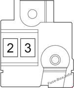
Diesel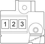
| № | Name | Amp | Circuit |
|---|---|---|---|
| 1 | GLOW DC/DC | 80 | Engine glow system |
| 2 | MAIN | 80 | “BBC”, “S-HORN”, “ST”, “D/L NO.2”, “D.C.C.”, “STR LOCK”, “ETCS”, “HAZ”, “AM2”, “ECU-B NO.2”, “R/I”, “H-LP MAIN”, “H-LP RH HI”, “H-LP LH HI”, “H-LP RH LO”, “H-LP LH LO”, “MMT” fuses |
| 3 | ALT | 120 | “PWR HTR”, “EPS”, “ABS NO.2”, “DEF”, “PTC”, “HTR”, “RDI FAN”, “ABS NO.1”, “TAIL NO.2”, “PANEL”, “DOOR R/R”, “DOOR P”, “ECU-IG NO.1”, “ECU-IG NO.2”, “A/C”, “GAUGE”, “WASHER”, “WIPER”, “WIPER RR”, “P/W”, “DOOR R/L”, “DOOR”, “CIG”, “ACC”, “D/L”, “OBD”, “FOG RR”, “STOP”, “AM1”, “FOG FR”, “D-D/L”, “SHADE”, “S-HTR” fuses |


