

Fuse Layout Toyota Tacoma 2001-2004
Contents
Cigar lighter (power outlet) fuses in the Toyota Tacoma are the fuse #2 “ACC” (Cigarette lighter) in the Instrument panel fuse box, and fuse #19 “PWR OUTLET” (Power outlet) in the Engine Compartment Fuse Box.
Table of Contents
Passenger Compartment Overview
Passenger Compartment Overview
Passenger Compartment Fuse Box
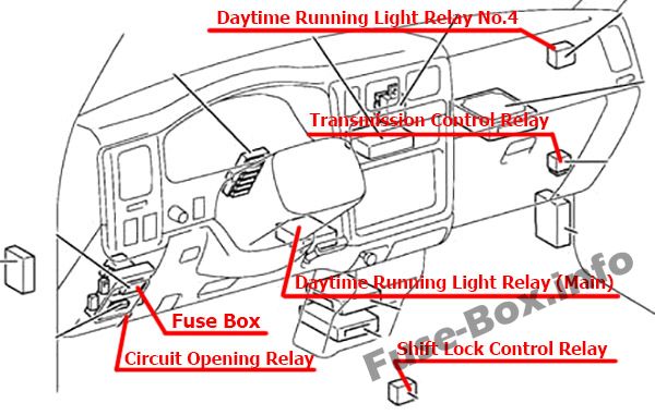
Fuse box location
The fuse box is located on the driver’s side of the instrument panel, behind the cover.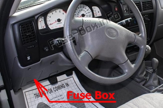
Fuse box diagram
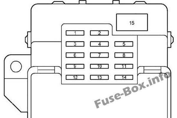
Assignment of the fuses in the Passenger Compartment
| № | Name | Amp | Designation |
|---|---|---|---|
| 1 | – | – | Not used |
| 2 | ACC | 15 | Cigarette lighter, clock, power rearview mirrors, back-up lights, automatic transmission shift lock system, SRS airbag system, seat belt pretensioners, car audio system |
| 3 | ECU-IG | 15 | Cruise control system, anti-lock brake system, automatic transmission shift lock system, SRS airbag system |
| 4 | GAUGE | 10 | Day time running light system, back-up lights, cruise control system, rear differential lock system, electronically controlled automatic transmission system, starting system, charging system, air conditioning system |
| 5 | ECU-B | 7.5 | SRS warning light, air conditioning system |
| 6 | TURN | 10 | Turn signal lights, emergency flashers |
| 7 | IGN | 7.5 | Gauges and meters, SRS airbag system, seat belt pretensioners, multiport fuel injection system/sequential multiport fuel injection system |
| 8 | HORN.HAZ | 15 | Emergency flashers, horns |
| 9 | WIPER | 20 | Windshield wipers and washer |
| 10 | – | – | Not used |
| 11 | STA | 7.5 | Clutch start cancel system, starting system |
| 12 | 4WD | 20 | A.D.D. control system, four-wheel drive control system, rear differential lock system |
| 13 | – | – | Not used |
| 14 | STOP | 10 | Stop lights, high mounted stoplight, cruise control system, anti-lock brake system, multiport fuel injection system/sequential multiport fuel injection system |
| 15 | POWER | 30 | Power windows, power seat |
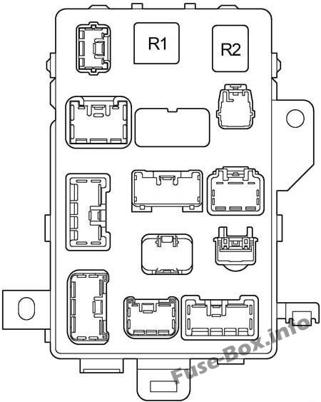
| № | Relay |
|---|---|
| R1 | Flasher |
| R2 | Power relay (power windows, power seat) |
Engine Compartment Fuse Box
Engine Compartment Fuse Box
Fuse box location
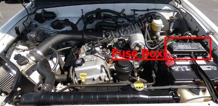
Fuse box diagram
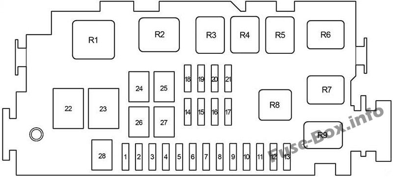
Assignment of the fuses and relay in the Engine Compartment
| № | Name | Amp | Designation |
|---|---|---|---|
| 1 | DRL | 7.5 | Daytime running light system |
| 2 | HEAD (RH) | 10 | Right-hand headlight |
| 2 | HEAD (HI RH) | 10 | with DRL: Right-hand headlight (high beam), high beam indicator light |
| 3 | HEAD (LH) | 10 | Left-hand headlight |
| 3 | HEAD (HI LH) | 10 | with DRL: Left-hand headlight (high beam) |
| 4 | HEAD (LO RH) | 10 | with DRL: Right-hand headlight (low beam) |
| 5 | HEAD (LO LH) | 10 | with DRL: Left-hand headlight (low beam) |
| 6 | TAIL | 10 | Tail lights, licence plate lights |
| 7 | – | – | Not used |
| 8 | A.C | 10 | Air conditioning system |
| 9 | – | – | Not used |
| 10 | – | – | Not used |
| 11 | – | – | Not used |
| 12 | – | – | Not used |
| 13 | – | – | Not used |
| 14 | ECTS | 15 | Multiport fuel injection system/sequential multiport fuel injection system |
| 14 | FOG | 15 | Fog light |
| 15 | DOME | 15 | Car audio system, interior light, clock, personal lights, door courtesy light, day time running light system, gauges and meters |
| 16 | OBD | 7.5 | On-board diagnosis system |
| 17 | EFI | 20 | Multiport fuel injection system/sequential multiport fuel injection system |
| 18 | ALT-S | 7.5 | Charging system |
| 19 | PWR OUTLET | 15 | Power outlet |
| 20 | – | – | Not used |
| 21 | – | – | Not used |
| 22 | ABS | 60 | Anti-lock brake system, traction control system, “AUTO LSD” system, vehicle stability control system |
| 23 | ALT | 120 | All components in “CAM1”, “HEATER”, “A.C”, “TAIL”, “ALT-S” and “PWR OUTLET” fuses |
| 24 | HEATER | 50 | All components in “A.C” fuse |
| 25 | AM1 | 40 | Starting system |
| 26 | J/B | 50 | All components in “POWER”, “HORN-HAZ”, “STOP” and “ECU-B” fuses |
| 27 | AM2 | 30 | Ignition system, multiport fuel injection system/sequential fuel injection system |
| 28 | ABS2 | 30 | without vehicle stability control system: Anti – lock brake system, traction control system, “AUTO LSD” system, vehicle stability control system |
| 28 | ABS2 | 50 | with vehicle stability control system: Anti-lock brake system, traction control system, “AUTO LSD” system, vehicle stability control system |
| Relay | |||
| R1 | Starter | ||
| R2 | Heater | ||
| R3 | Not used | ||
| R4 | Taillights | ||
| R5 | Not used | ||
| R6 | Power outlet | ||
| R7 | EFI relay | ||
| R8 | Headlight | ||
| R9 | Dimmer |


