

See other Toyota Hilux:


Fuse Layout Toyota Hilux 2004-2015
Contents

Cigar lighter (power outlet) fuses in the Toyota Hilux are the fuses #5 “PWR OUT” (Power outlet) and #9 “CIG” (Cigarette lighter) in the Instrument panel fuse box.
Table of Contents
Passenger Compartment Fuse Box
Fuse box location
Left-hand drive vehicles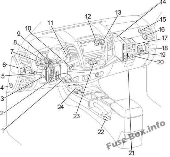
Right-hand drive vehicles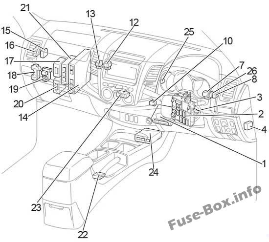
- A/C Amplifier (with Air Conditioner)
Viscous Heater Amplifier (without Air Conditioner) - Fuse Box / Integration Relay
- Transponder Key Amplifier
- 4WD Control ECU (Rear Differential Lock)
- LHD:Tail Lamp Relay (Aug. 2006 – Jun. 2011)
- LHD:Daytime Running Light Relay
- Turn Signal Flasher
- Magnet Clutch Relay
- LHD:Tail Lamp Relay (Before Aug. 2006)
LHD: Rear Fog Lamp Relay (From Aug. 2006) - Junction Connector
- LHD:Tail Lamp Relay (From Jun. 2011)
- PTC Heater Relay (No.2)
- PTC Heater Relay (No.1)
- Engine ECU
- Door Control Receiver
- Theft Warning ECU
- 4WD Control ECU
- Relay Box (From Jun. 2011)
- Relay Box (Before Jun. 2011)
- Turbo Motor Driver
- Transmission Control ECU
- Shift Lock Control ECU
- A/C Control Assembly
- Airbag Sensor Assembly Center
- RHD:Tail Lamp Relay
- RHD:Rear Fog Lamp Relay
The fuse box is located under the steering wheel, behind the cover.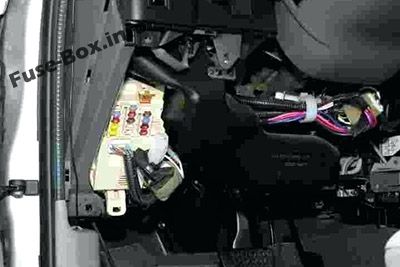
Left-hand drive vehicles
Right-hand drive vehicles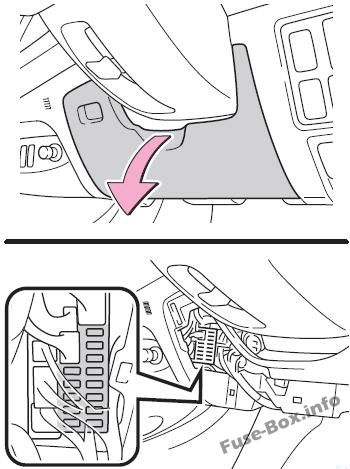
Fuse box diagram
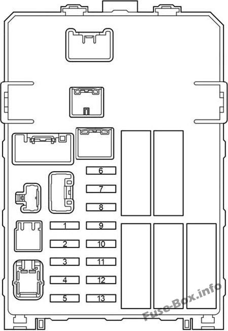
Assignment of the fuses in the Passenger Compartment Fuse box
| № | Name | Amp | Circuit |
|---|---|---|---|
| 1 | INJ | 15 | Multiport fuel injection system/sequential multiport fuel injection system |
| 2 | OBD | 7.5 | On-board diagnosis system |
| 3 | STOP | 10 | Stop lights, high mounted stoplight, multiport fuel injection system/sequential multiport fuel injection system, ABS, TRC, VSC and shift lock control system |
| 4 | TAIL | 10 | Instrument panel light, front fog lights, headlight beam level control system, front position lights, tail lights, license plate lights, multiport fuel injection system/sequential multiport fuel injection system, multi-information display, daytime running light system and automatic headlight system |
| 5 | PWR OUT | 15 | Power outlet |
| 6 | ST | 7.5 | Starting system, gauges and meters and multiport fuel injection system/sequential multiport fuel injection system |
| 7 | A/C | 10 | Air conditioning system |
| 8 | MET | 7.5 | Gauges and meters and DPF system |
| 9 | CIG | 15 | Cigarette lighter |
| 10 | ACC | 7.5 | Audio system, power outlet, clock, power rear view mirror control system, shift lock control system and multi-information display |
| 11 | IGN | 7.5 | Multiport fuel injection system/sequential multiport fuel injection system, SRS airbags and fuel pump |
| 12 | WIP | 20 | Windshield wiper and washer |
| 13 | ECU-IG & GAUGE | 10 | Air conditioning system, charging system, rear differential lock system, ABS, TRC, VSC, emergency flashers, turn signal lights, back-up lights, multiport fuel injection system/sequential multiport fuel injection system, shift lock control system, rear window defogger, headlights, door courtesy switches, power door lock system, wireless remote control system, steering sensor, daytime running light system, cruise control, headlight cleaners, seat heaters, outside rear view mirror defoggers, multi-information display and passenger’s seat belt reminder light |
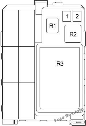
| № | Name | Amp | Circuit |
|---|---|---|---|
| 1 | AM1 | 40 | Rear differential lock system, ABS, TRC, VSC, “ACC”, TIG”, “ECU-IG & GAUGE”, and “WIP” fuses |
| 2 | IG1 | 40 | “PWR”, “S-HTR”, “4WD”, “DOOR”, “DEF” and “MIR HTR” fuses |
| Relay | |||
| R1 | Power outlet (PWR OUT) | ||
| R2 | Heater (HTR) | ||
| R3 | Integration relay |
Relay Box
It is located behind the glovebox.
Left-hand drive vehicles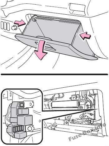
Right-hand drive vehicles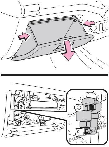
Until Jun.2011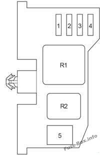
Passenger Compartment Relay Box (Until Jun.2011)
| № | Name | Amp | Circuit |
|---|---|---|---|
| 1 | DOOR | 25 | Power door lock system and power windows |
| 2 | DEF | 20 | Rear window defogger and multiport fuel injection system/sequential multiport fuel injection system |
| 3 | S-HTR | 15 | Seat heaters |
| 4 | 4WD | 20 | Rear differential lock system, ABS, TRC and VSC |
| 5 | PWR | 30 | Power windows |
| Relay | |||
| R1 | Ignition (IG1) | ||
| R2 | Rear window defogger (DEF) |
Since Jun.2011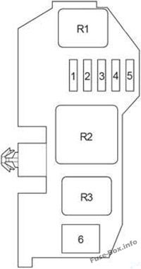
Passenger Compartment Relay Box (Since Jun.2011)
| № | Name | Amp | Circuit |
|---|---|---|---|
| 1 | MIR HTR | 15 | Before Nov. 2011: Outside rear view mirror defoggers |
| 1 | DOOR | 25 | From Nov. 2011: Power door lock system and power windows |
| 2 | DOOR | 25 | Before Nov. 2011: Power door lock system and power windows |
| 2 | DEF | 20 | From Nov. 2011: Rear window defogger and multiport fuel injection system/sequential multiport fuel injection system |
| 3 | DEF | 20 | Before Nov. 2011: Rear window defogger and multiport fuel injection system/sequential multiport fuel injection system |
| 3 | S-HTR | 15 | From Nov. 2011: Seat heaters |
| 4 | S-HTR | 15 | Before Nov. 2011: Seat heaters |
| 4 | 4WD | 20 | From Nov. 2011: Rear differential lock system, ABS, TRC and VSC |
| 5 | 4WD | 20 | Before Nov. 2011: Rear differential lock system, ABS, TRC and VSC |
| 5 | MIR HTR | 15 | From Nov. 2011: Outside rear view mirror defoggers |
| 6 | PWR | 30 | Power windows |
| Relay | |||
| R1 | Outside rear view mirror defoggers (MIR HTR) | ||
| R2 | Ignition (IG1) | ||
| R3 | Rear window defogger (DEF) |
Fuse Box in the Engine Compartment
Fuse box location
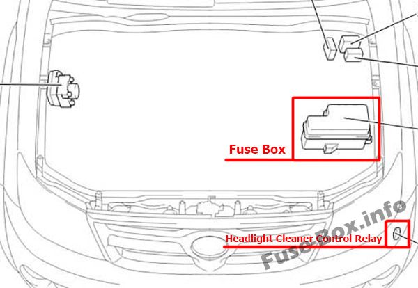
The fuse box is located in the engine compartment (left-side).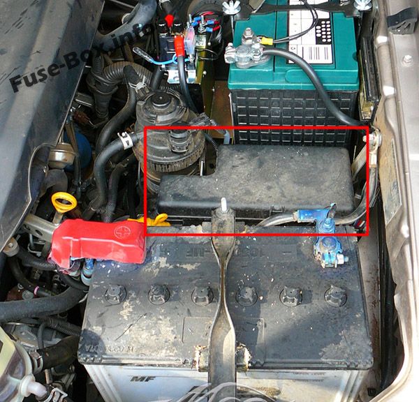
Fuse box diagram
Assignment of the fuses in the Engine Compartment
| № | Name | Amp | Circuit |
|---|---|---|---|
| 1 | – | 25 | Spare fuse |
| 2 | – | 15 | Spare fuse |
| 3 | – | 10 | Spare fuse |
| 4 | FOG | 7.5 | Europe, Morocco: From Aug. 2012 – Aug. 2013: Front fog lights From Aug. 2013: Front fog lights |
| 4 | FOG | 15 | Before Aug. 2013: Front fog lights Except Europe, Morocco: From Aug. 2012 – Aug. 2013: Front fog lights |
| 5 | HORN | 10 | Horn |
| 6 | EFI | 25 | Multiport fuel injection system/sequential multiport fuel injection system |
| 7 | – | – | – |
| 8 | H-LP RL | 20 | Before Jun. 2011: Right-hand headlight (Low) |
| 8 | H-LP RL | 15 | From Jun. 2011: Right-hand headlight (Low) |
| 9 | H-LP LL | 20 | Before Jun. 2011: Left-hand headlight (Low) |
| 9 | H-LP LL | 15 | From Jun. 2011: Left-hand headlight (Low) |
| 10 | H-LP RH | 20 | Before Jun. 2011: Right-hand headlight (High) and right-hand headlight (Low) |
| 10 | H-LP RH | 15 | From Jun. 2011: Right-hand headlight (High) and right-hand headlight (Low) |
| 11 | H-LP LH | 20 | Before Jun. 2011: Left-hand headlight (High) and left-hand headlight (Low) |
| 11 | H-LP LH | 15 | From Jun. 2011: Left-hand headlight (High) and left-hand headlight (Low) |
| 12 | EFI NO.2 | 10 | Multiport fuel injection system/sequential multiport fuel injection system |
| 13 | ECU-IG NO.2 | 10 | Multiport fuel injection system/ sequential multiport fuel injection system |
| 14 | ECU-B | 7.5 | Before Aug. 2008: Door courtesy switches, power door lock system, wireless remote control system, steering sensor and headlights |
| 14 | ECU-B | 10 | From Aug. 2008: Door courtesy switches, power door lock system, wireless remote control system, steering sensor and headlights |
| 15 | RAD | 15 | Before Aug. 2013: Audio system |
| 15 | RAD | 20 | From Aug. 2013: Audio system |
| 16 | DOME | 7.5 | Interior lights, engine switch light, personal light, gauges and meters, clock, multi-information display, wireless remote control system, daytime running light system and fog light |
| 17 | A/F | 20 | Emission control system |
| 18 | ETCS | 10 | Multiport fuel injection system/ sequential multiport fuel injection system, electric throttle control system |
| 19 | ALT-S | 7.5 | Charging system |
| 20 | TURN-HAZ | 15 | Emergency flashers and turn signal lights |
| 21 | – | – | – |
| 22 | ECU-B NO.2 | 7.5 | Air conditioning system |
| 23 | DCC | 30 | “ECU-B”, “DOME” and “RAD” fuses |
| 24 | PTC NO.1 | 50 | Power heater |
| 25 | H-LP CLN | 30 | Before Jun. 2011: Headlight cleaners |
| 25 | PWR SEAT | 30 | Power seat |
| 26 | PTC NO.2 | 50 | Europe: From Aug. 2010 – Jun. 2011 (without Automatic A/C): Power heater; From Jun. 2011: Power heater |
| 26 | PTC NO.2 | 30 | Europe: Before Jun. 2011 (with Automatic A/C): Power heater; Before Aug. 2010 (without Automatic A/C): Power heater Australia: Power heater |
| 27 | ABS NO.1 | 40 | Before Aug. 2008: ABS, TRC and VSC |
| 27 | H-LP CLN | 40 | From Jun. 2011: Headlight cleaners |
| 28 | FR HTR | 40 | Before Aug. 2009: Air conditioning system, “A/C” fuse |
| 28 | FR HTR | 50 | From Aug. 2009: Air conditioning system, “A/C” fuse |
| 29 | ABS NO.2 | 30 | ABS, TRC and VSC |
| 30 | ABS NO.1 | 40 | From Aug. 2008: ABS, TRC and VSC |
| 31 | ALT | 100 | Charging system, “PWR SEAT”, “HLP CLN”, “FR HTR”, “AMI”, “IG1”, “PTC NO.1”, “PTC NO.2”, “PWR OUT”, “STOP”, “TAIL” and “OBD” fuses |
| 32 | GLOW | 80 | Engine glow system |
| 33 | BATT P/I | 50 | “FOG”, “HORN” and “EFI” fuses |
| 34 | AM2 | 30 | Engine starter, “ST”, “IGN”, “INJ” and “MET” fuses |
| 35 | MAIN | 40 | “H-LP RH”, “H-LP LH”, “H-LP RL” and “H-LP LL” fuses |
| 36 | A/PUMP | 50 | Multiport fuel injection system/sequential multiport fuel injection system |
| Relay | |||
| R1 | Dimmer (DIM) | ||
| R2 | Headlight (H-LP) | ||
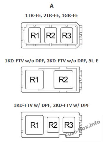
| A | |||
| R1 | Starter (ST) | ||
| R2 | 1TR-FE, 2TR-FE, 1GR-FE: Air fuel ratio sensor (A/F) 1KD-FTV w/o DPF, 2KD-FTV w/o DPF, 5L-E: Engine glow system (GLOW) 1KD-FTV w/ DPF, 2KD-FTV w/ DPF: Air fuel ratio sensor (A/F) |
||
| R3 | 1TR-FE, 2TR-FE, 1GR-FE: Fuel pump (F/PMP) 1KD-FTV w/ DPF, 2KD-FTV w/ DPF: – |


