

See other Toyota HiAce:

Fuse Layout Toyota HiAce 2005-2013
Contents

Cigar lighter (power outlet) fuse in the Toyota HiAce is the fuse #23 “CIG” in the Instrument panel fuse box.
Table of Contents
Passenger Compartment Fuse Box
Passenger Compartment Fuse Box
Fuse box location
Left-hand drive vehicles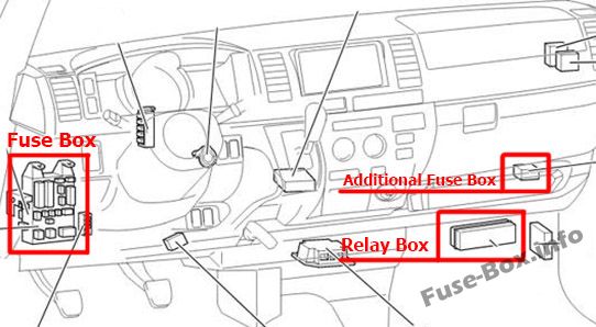
Right-hand drive vehicles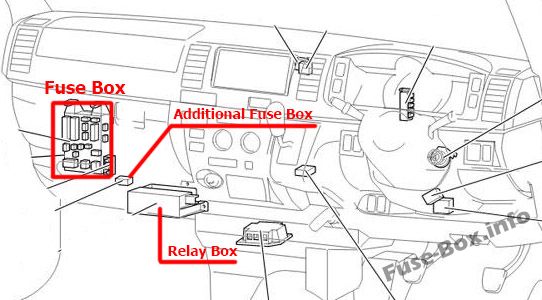
The fuse box is located under the instrument panel, under the cover.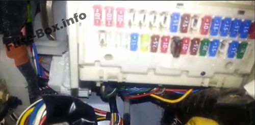
Fuse box diagram
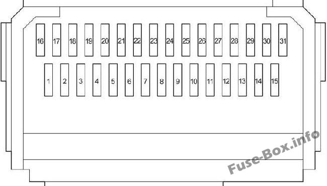
Assignment of the fuses in the Passenger Compartment
| № | Name | Amp | Circuit |
|---|---|---|---|
| 1 | – | – | – |
| 2 | ACCL INT LCK | 25 | – |
| 3 | WIP | 25 | Windshield wipers |
| 4 | RR WIP-WSH | 15 | Rear window wipers and washer |
| 5 | WSH | 20 | Window wipers and washer, rear window wipers and washer |
| 6 | ECU-IG | 7.5 | Air conditioning system, automatic transmission shift lock control system, anti-lock brake system, sliding door closer system, multiport fuel injection system/sequential multiport fuel injection system, multiplex communication system |
| 7 | GAUGE | 10 | Gauges and meters, rear turn signal lights, stop/tail lights, back-up lights, rear window defogger, electric cooling fans, charging system, air conditioning system, power windows |
| 8 | OBD | 7.5 | On-board diagnosis system |
| 9 | STOP | 10 | Rear turn signal lights, stop/tail lights, back-up lights, high-mounted stoplight |
| 10 | – | – | – |
| 11 | DOOR | 30 | Power windows, power door lock system |
| 12 | RR HTR | 15 | Air conditioning system |
| 13 | – | – | – |
| 14 | FR FOG | 10 / 15 | Front fog light |
| 15 | AM1 | 30 | All components in “ACC”, and “CIG” fuses, starting system |
| 16 | TAIL | 10 | Front position lights, rear turn signal lights, stop/tail lights, back-up lights, license plate lights, clock, instrument panel light, multiport fuel injection system/sequential multiport fuel injection system |
| 17 | PANEL | 10 | Instrument panel light |
| 18 | A/C | 10 | Air conditioning system |
| 19 | – | – | – |
| 20 | – | – | – |
| 21 | – | – | – |
| 22 | – | – | – |
| 23 | CIG | 15 | Cigarette lighter |
| 24 | ACC | 7.5 | Power rear view mirror, automatic transmission shift lock control system |
| 25 | – | – | |
| 26 | ELS | 10 | Multiport fuel injection system/sequential multiport fuel injection system |
| 27 | AC100V | 15 | – |
| 28 | RR FOG | 15 | Rear turn signal lights, stop/tail lights, back-up lights |
| 29 | – | – | – |
| 30 | IGN | 15 | Multiport fuel injection system/sequential multiport fuel injection system, electronic throttle control system, SRS airbag system |
| 31 | MET IGN | 10 | Gauges and meters |
| № | Name | Amp | Circuit |
|---|---|---|---|
| 1 | POWER | 30 | Power windows |
| 2 | DEF | 30 | Rear window defogger |
| 3 | – | – | – |
| Relay | |||
| R1 | Ignition (IG1) | ||
| R2 | Heater (HTR) | ||
| R3 | Flasher |
Relay Box
The relay box is located under the instrument panel, behind the cover.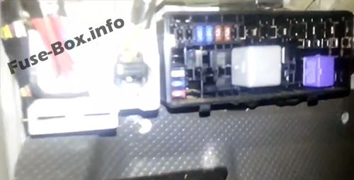
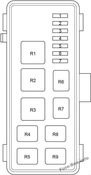
Passenger Compartment Relay Box
| № | Name | Amp | Circuit |
|---|---|---|---|
| 1 | HEAD LL | 15 | – |
| 2 | HEAD RL | 15 | – |
| 3 | HEAD LH | 15 | Left-hand headlight |
| 4 | HEAD RH | 15 | Right-hand headlight |
| 5 | ST | 7.5 | Starting system, multiport fuel injection system/sequential multiport fuel injection system, gauges and meters |
| 6 | A/C NO.3 | 7.5 | Air conditioning system |
| 7 | – | – | – |
| Relay | |||
| R1 | – | ||
| R2 | Headlight (HEAD) | ||
| R3 | – | ||
| R4 | Starter (ST) | ||
| R5 | (OSV) | ||
| R6 | – | ||
| R7 | Front fog light (FR FOG) | ||
| R8 | Air conditioner compressor clutch (MG CLT) | ||
| R9 | (INJ/IGN) |
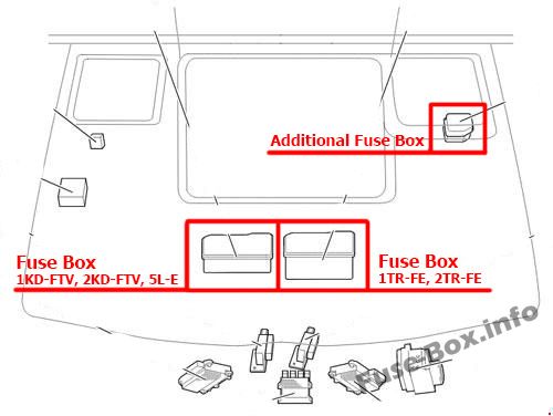
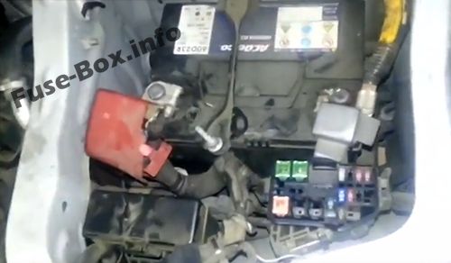
Fuse Boxes in the Engine Compartment
Fuse Boxes in the Engine Compartment
Fuse box location
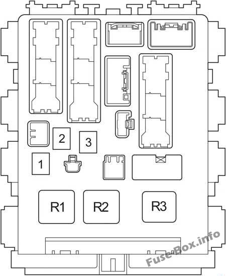
Fuse box diagram
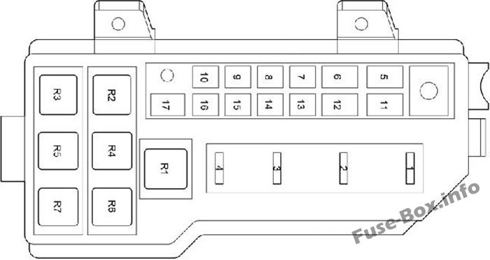
Assignment of the fuses in the Engine Compartment
| № | Name | Amp | Circuit |
|---|---|---|---|
| 1 | A/F | 15 | 1TR-FE, 2TR-FE: Multiport fuel injection system/sequential multiport fuel injection system |
| 1 | EDU | 25 | 1KD-FTV, 2KD-FTV, 5L-E: Multiport fuel injection system/sequential multiport fuel injection system |
| 2 | HAZ-HORN | 15 | Horns, emergency flasher |
| 3 | EFI | 20 | 1TR-FE, 2TR-FE: Electronically controlled fuel pump, multiport fuel injection system/sequential multiport fuel injection system, electronic throttle control system |
| 3 | EFI | 25 | 1KD-FTV, 2KD-FTV, 5L-E: Electronically controlled fuel pump, multiport fuel injection system/sequential multiport fuel injection system, electronic throttle control system |
| 4 | – | – | – |
| 5 | ALT | 140 | All components in “MAIN3”, “FAN1”, “FAN2” and “GLOW” fuses |
| 5 | ALT | 150 | Refrigerator Van: All components in “MAIN3”, “FAN1”, “FAN2” and “GLOW” fuses |
| 6 | A/PUMP | 50 | 1TR-FE, 2TR-FE: Emission control system |
| 6 | GLOW | 80 | 1KD-FTV, 2KD-FTV, 5L-E: Engine glow system |
| 7 | MAIN 3 | 50 | All components in “A/F”, “HAZ-HORN” and “EFI” fuses |
| 8 | FAN 2 | 50 | Electric cooling fans |
| 9 | FAN 3 | 30 | 1KD-FTV, 2KD-FTV, 5L-E: Electric cooling fans |
| 10 | FAN 1 | 50 | Electric cooling fans |
| 11 | PTC1 | 50 | 1KD-FTV, 2KD-FTV: PTC Heater |
| 12 | MAIN4 | 120 | All components in “WELCAB”, “AC100V”, “RR FOG”, “RR HTR”, ”OBD”, “STOP”, “AMI”, “DOOR”, “FR FOG”, “PWR”, “DEF”, “ELS”, “TAIL”, “PANEL”, “ECU-IG”, “WIP”, “WSH”, “GAUGE”, “RR WIP-WSH”and “A/C” fuses |
| 13 | – | – | – |
| 14 | HTR | 40 | Air conditioning system |
| 15 | – | – | – |
| 16 | RR CLR | 30 | Rear air conditioner |
| 17 | PTC2 | 50 | 1KD-FTV, 2KD-FTV: PTC Heater |
| Relay | |||
| R1 | 1TR-FE, 2TR-FE: Rear air conditioner (RR CLR) | ||
| R2 | 1KD-FTV, 2KD-FTV, 5L-E: Engine glow system (GLOW) | ||
| R3 | 1KD-FTV, 2KD-FTV, 5L-E: Rear air conditioner (RR CLR) | ||
| R4 | 1KD-FTV, 2KD-FTV: PTC Heater (PTC2) | ||
| R5 | Electric cooling fans (FAN1) | ||
| R6 | 1KD-FTV, 2KD-FTV: PTC Heater (PTC1) | ||
| R7 | Electric cooling fans (FAN2) |
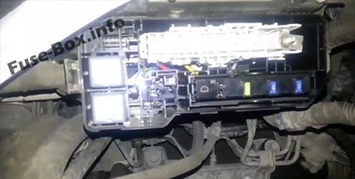
Additional Fuse Box
Until April 2012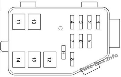
Since April 2012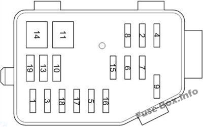
Engine Compartment Additional Fuse Box
| № | Name | Amp | Circuit |
|---|---|---|---|
| 1 | ECU-B | 10 | Multiplex communication system, sliding door closer system, air conditioning system, wireless remote control system |
| 2 | ETCS | 10 | 1TR-FE (from Apr. 2012), 2TR-FE: Electronic throttle control system |
| 2 | A/F | 15 | 1KD-FTV with DPF: A/F heater, Electronically controlled fuel pump |
| 3 | PSD | 25 | Sliding door closer system |
| 4 | ABS SOL | 25 | Anti-lock brake system |
| 5 | TVSS | 15 | – |
| 6 | DOME | 10 | Personal lights, interior lights, step lights, gauges and meters |
| 7 | RADIO | 15 | Audio system |
| 8 | ALT-S | 7.5 | Charging |
| 9 | D.C.C | 30 | All components in “RADIO” and “DOME” fuses |
| 10 | HEAD | 40 | Headlight |
| 11 | ABS MTR | 40 | Anti-lock brake system |
| 12 | – | – | – |
| 13 | RR DOOR | 30 | Sliding door closer system |
| 14 | AM2 | 30 | All components in “IGN” and “MET IGN” fuses, starting system, multiport fuel injection system/sequential multiport fuel injection system |
| 15 | – | – | – |
| 16 | – | – | – |
| 17 | – | – | – |
| 18 | – | – | – |
| 19 | – | – | – |


