


Fuse Layout Toyota Corolla 2003-2008
Contents
Cigar lighter (power outlet) fuses in the Toyota Corolla are the fuses #32 “CIG”, #25 “AM1” and #30 “P/POINT” in the Instrument panel fuse box.
Table of Contents
Passenger Compartment Fuse Box
Passenger Compartment Fuse Box
Fuse Box Location
The fuse box is located below the driver’s side of the instrument panel.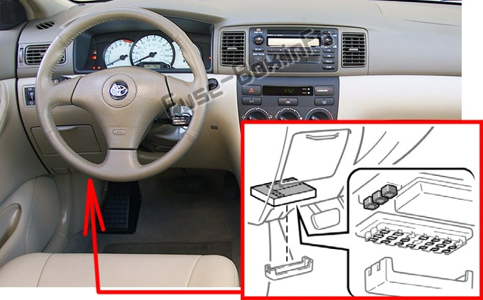
Fuse Box Diagram
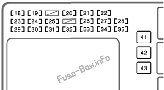
Assignment of the fuses in the instrument panel
| № | Name | Amp | Description |
|---|---|---|---|
| 18 | TAIL | 15A | Tail lights, license plate lights, instrument panel lights, instrument cluster lights |
| 19 | OBD | 7.5A | On-board diagnosis system |
| 20 | P/W | 30A | No circuit |
| 21 | WIPER | 25A | Windshield wipers |
| 22 | AM2 | 15A | Charging system, multiport fuel injection system/sequential multi-port fuel injection system, starting system, SRS airbag system |
| 23 | STOP | 15A | Stop lights, high mounted stoplight, anti-lock brake system, shift lock control system, multiport fuel injection system/sequential multiport fuel injection system, cruise control system |
| 24 | DOOR | 25A | Power door lock system |
| 25 | AM1 | 25A | “CIG” fuse |
| 26 | ECU-IG | 10A | Electric cooling fan, anti-lock brake system, vehicle stability control system, traction control system, brake assist system, shift lock control system, cruise control system |
| 27 | RR WIPER | 15A | No circuit |
| 28 | A/C | 10A | Air conditioning system |
| 29 | INV | 15A | No circuit |
| 30 | P/POINT | 15A | Power outlet (in the rear console box) |
| 31 | ECU-B | 10A | Daytime running light system |
| 32 | CIG | 15A | Power outlet (on the instrument panel) or cigarette lighter, car audio system, clock, power rear view mirror control, shift lock control system |
| 33 | GAUGE | 10A | Gauges and meters, air conditioning system, daytime running light system, charging system, auto anti-glare inside rear view mirror, power windows, cruise control system, rear window defogger, back-up lights, front passenger’s seat belt reminder light |
| 34 | WASHER | 15A | Windshield washer |
| 35 | M-HTR/DEF I-UP | 10A | Engine control system |
| 41 | HTR | 40A | Air conditioning system |
| 42 | DEF | 40A | Rear window defogger, “M-HTR/DEF I-UP” fuse |
| 43 | POWER | 30A | Power windows, electric moon roof |
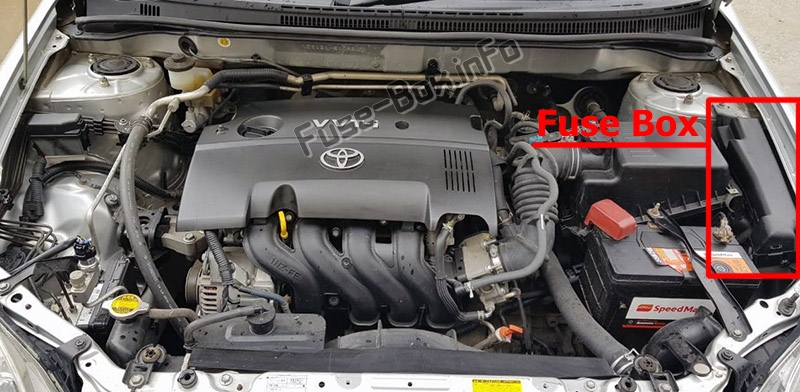
Engine Compartment Fuse Box
Engine Compartment Fuse Box
Fuse Box Location
Fuse Box Diagram
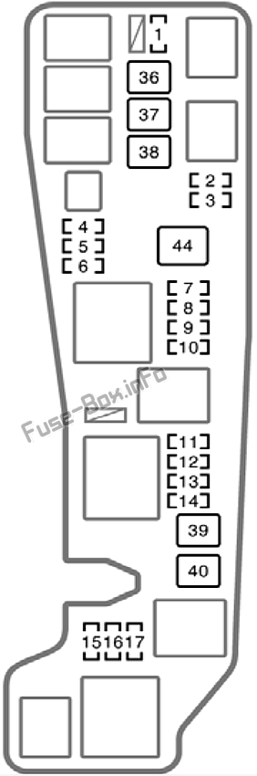
Assignment of the fuses in the engine compartment
| № | Name | Amp | Description |
|---|---|---|---|
| 1 | FOG | 15A | Front fog lights |
| 2 | HEAD LH UPR | 10A | Left-hand headlight (high beam) |
| 3 | HEAD RH UPR | 10A | Right-hand headlight (high beam), high beam indicator light |
| 4 | SPARE | 30A | Spare fuse |
| 5 | SPARE | 15A | Spare fuse |
| 6 | SPARE | 10A | Spare fuse |
| 7 | ETCS | 10A | 2003-2004: Not Used; 2005-2008 (1ZZ-FE engine): Electronic throttle control system |
| 8 | AMP | 30A | 2003-2004: Not Used; 2005-2008: Car audio system |
| 9 | MAIN | 30A | Starting system, “AM2” fuse |
| 10 | DOME | 15A | Car audio system, clock, personal lights, interior light, trunk light, open door warning light, wireless remote control system |
| 11 | HORN | 10A | Horn |
| 12 | HAZARD | 10A | Emergency flashers, turn signal lights |
| 13 | EFI | 15A or 20A | Multiport fuel injection system/sequential multiport fuel injection system, emission control system, “EFI2” fuse; (1ZZ-FE engine – 20A; 2ZZ-GE engine – 15A) |
| 14 | ALT-S | 5A | Charging system |
| 15 | HEAD LH LWR | 10A | Left-hand headlight (low beam) |
| 16 | HEAD RH LWR | 10A | Right-hand headlight (low beam) |
| 17 | EFI2 | 15A | 2003-2004: Not Used; 2005-2008 (1ZZ-FE engine): Multiport fuel injection system/ sequential multi-port fuel injection system, emission control system |
| 36 | ABS No.1 | 30A | 2003-2004: Anti-lock brake system; 2005-2008: Anti-lock brake system, vehicle stability control system, traction control system, brake assist system |
| 37 | RDI FAN | 30A | Electric cooling fan |
| 38 | ABS No.2 | 40A or 50A | Without vehicle stability control system (40A): Anti-lock brake system;
With vehicle stability control system (50A): Anti-lock brake system, vehicle stability control system, traction control system, brake assist system; |
| 39 | HEAD MAIN | 40A | “HEAD LH UPR”, “HEAD RH UPR”, “HEAD LH LWR” and “HEAD RH LWR” fuses |
| 40 | AIR PUMP | 50A | 2003-2004: Not Used; 2005-2006 (2ZZ-GE engine): Emission control system; 2007-2008: Not Used |
| 44 | ALT | 100A | Charging system, “ABS NO.1”, “ABS NO.2”, “RDI FAN”, “FOG”, “HTR”, “AM1”, “POWER”, “DOOR”, “ECU−B”, “TAIL”, “STOP”, “P/POINT”, “INV” and “OBD” fuses |


