

Fuse Layout Toyota Avalon 2005-2012
Contents

Cigar lighter (power outlet) fuses in the Toyota Avalon are the fuses #29 “CIG” (Cigarette lighter) and #30 “PWR OUTLET” (Power outlet) in the Instrument panel fuse box.
Table of Contents
Passenger compartment overview
Passenger Compartment Fuse Box
Passenger Compartment Fuse Box
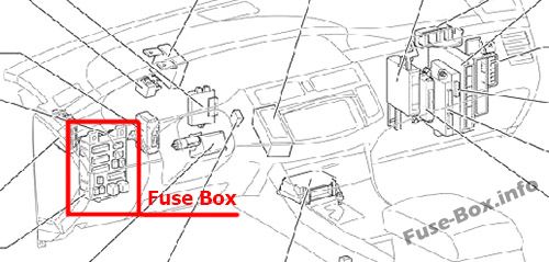
Fuse box location
The fuse box is located under the instrument panel (on the driver’s side), under the cover.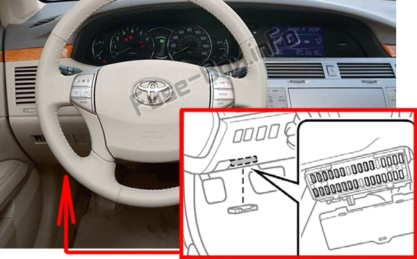
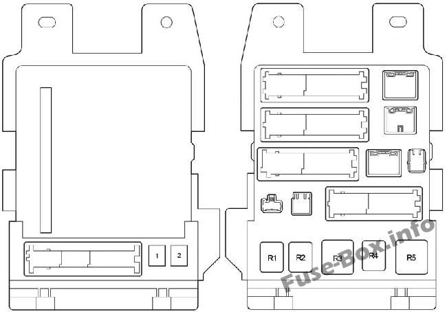
Fuse box diagram
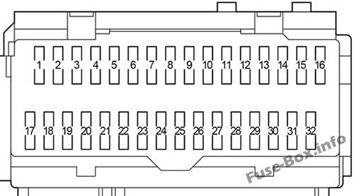
Assignment of the fuses in the Passenger Compartment
| № | Name | Amp | Circuit |
|---|---|---|---|
| 1 | RR DOOR | 25 | 2005-2009: Power window (for rear right passenger) |
| 1 | RR DOOR | 20 | 2010-2012: Power window (for rear right passenger) |
| 2 | RL DOOR | 25 | 2005-2009: Power window (for rear left passenger) |
| 2 | RL DOOR | 20 | 2010-2012: Power window (for rear left passenger) |
| 3 | FR DOOR | 25 | 2005-2009: Power window (front passenger), driving position memory system |
| 3 | FR DOOR | 20 | 2010-2012: Power window (front passenger), driving position memory system |
| 4 | FOG | 15 | Front fog lights |
| 5 | OBD | 7.5 | On-board diagnosis system |
| 6 | MPX-B | 7.5 | Multiplex communication system |
| 7 | – | – | – |
| 8 | P/W | 25 | 2005-2009: Power widow, driving position memory system |
| 8 | FL DOOR | 20 | 2010-2012: Power window, driving position memory system |
| 9 | FUEL OPN | 7.5 | Fuel filler door opener |
| 10 | AM1 | 7.5 | Multiport fuel injection system/sequential multiport fuel injection system, starting system, ignition system |
| 11 | A/C | 7.5 | Air conditioning system |
| 12 | S-HTR | 20 | 2008-2012: Air conditioning system |
| 13 | DOOR NO.2 | 25 | Multiplex communication system |
| 14 | S/ROOF | 30 | Electric moon roof |
| 15 | TAIL | 10 | Parking lights, license plate lights, tail lights, front and rear side marker lights |
| 16 | PANEL | 7.5 | Seat heaters, navigation system, emergency flasher, electronically controlled automatic transmission system, glove box light, instrument panel lights, power outlets |
| 17 | ECU IG NO.1 | 7.5 | 2005-2006: Center display, shift lock control system, electric moon roof, multiplex communication system |
| 17 | ECU IG NO.1 | 10 | 2007-2012: Center display, shift lock control system, electric moon roof, multiplex communication system, tire pressure monitoring (warning) system |
| 18 | ECU IG NO.2 | 7.5 | Anti-lock brake system, dynamic laser cruise control system, automatic headlight leveling system, vehicle stability control system, multiplex communication system |
| 19 | HTR | 7.5 | Air conditioning system, instrument panel lights, electric cooling fan |
| 20 | A/C COMP | 7.5 | Air conditioning system |
| 21 | S-HTR | 20 | 2005-2007: Air conditioning system |
| 22 | GAUGE NO.1 | 10 | Back-up lights, navigation system, emergency flashers |
| 23 | WIP | 30 | Windshield wipers |
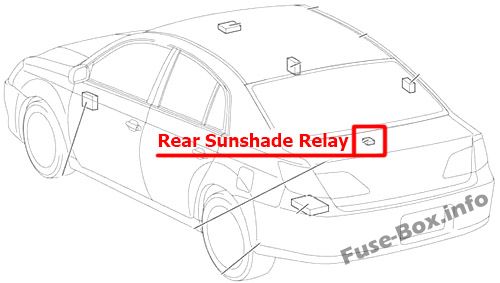
| 24 | RR S/SHADE | 10 | Rear electric sunshade |
| 25 | – | – | Not used |
| 26 | IGN | 10 | Multiport fuel injection system/sequential multiport fuel injection system, engine immobilizer system, SRS airbag system, front passenger occupant classification system, smart key system, starter system |
| 27 | GAUGE NO.2 | 7.5 | Gauges and meters, center display |
| 28 | ECU-ACC | 7.5 | Power rear view mirrors, center display, shift lock system, multiplex communication system |
| 29 | CIG | 15 | Cigarette lighter |
| 30 | PWR OUTLET | 15 | Power outlet |
| 31 | RADIO NO.2 | 7.5 | Audio system |
| 32 | MIR HTR | 10 | Outside rear view mirror defoggers |
| № | Name | Amp | Circuit |
|---|---|---|---|
| 1 | P/SEAT | 30 | Power seats |
| 2 | POWER | 30 | Power windows |
| Relay | |||
| R1 | Fog Lights | ||
| R2 | Tail Lights | ||
| R3 | Accessory Relay (ACC) | ||
| R4 | Power Relay (PWR) | ||
| R5 | Ignition (IG1) |
Engine Compartment Fuse Box
Engine Compartment Fuse Box
Fuse box location
The fuse box is located in the engine compartment (left-side)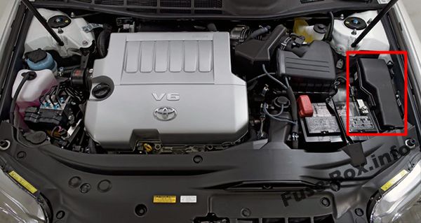
Fuse box diagram
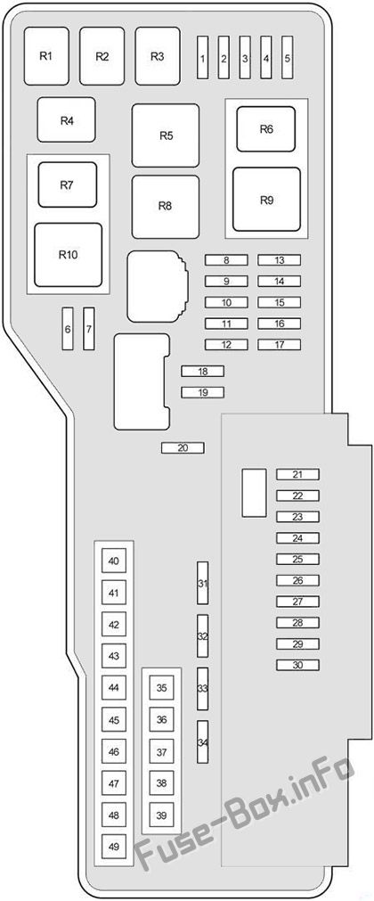
Assignment of the fuses and relay in the Engine Compartment
| № | Name | Amp | Circuit |
|---|---|---|---|
| 1 | EFI NO.2 | 10 | Multiport fuel injection system/sequential multiport fuel injection system |
| 2 | STOP NO.2 | 7.5 | Stop lights, high mounted stoplight, vehicle stability control system, anti-lock brake system |
| 3 | RADAR CC | 7.5 | 2005-2010: Vehicle stability control system |
| 4 | HEAD RH LWR | 15 | Right-hand headlight (low beam) |
| 5 | HEAD LH LWR | 15 | Left-hand headlight (low beam) |
| 6 | STOP No.3 | 7.5 | 2008-2012: Electronic controlled transmission system, multiport fuel injection system/sequential multiport fuel injection system |
| 7 | INJ | 15 | Multiport fuel injection system/sequential multiport fuel injection system |
| 8 | – | – | – |
| 9 | STOP NO.1 | 15 | Multiplex communication system |
| 10 | STR LOCK | 25 | 2005-2010: Steering lock system |
| 10 | STR LOCK | 15 | 2011-2012: Steering lock system |
| 11 | IMMOBI | 7.5 | 2005-2007: Engine immobilizer system, smart key system |
| 11 | EFI No.3 | 7.5 | 2008-2012: Smart key system, electronic controlled transmission system |
| 12 | AMP | 30 | Audio system |
| 13 | – | – | – |
| 14 | – | – | Short Pin NO.1 |
| 15 | RAD NO.1 | 15 | Audio system, center display, navigation system |
| 16 | ECU-B | 10 | Center display, multiplex communication system |
| 17 | DOME | 7.5 | Gauges and meters, clock, front personal lights, door courtesy lights, garage door opener, rear personal lights, trunk light |
| 18 | TURN/HAZ | 15 | Turn signal lights |
| 19 | IG2 | 25 | Multiport fuel injection system/sequential multiport fuel injection system |
| 20 | – | – | – |
| 21 | S-HORN | 7.5 | Horn |
| 22 | WASHER | 20 | Windshield washer |
| 23 | A/F | 25 | Air fuel ratio sensor |
| 24 | HEAD RH UPR | 15 | Right-had headlight (high beam) |
| 25 | HEAD LH UPR | 15 | Left-hand headlight (high beam) |
| 26 | – | – | – |
| 27 | – | – | – |
| 28 | HORN | 10 | Horn |
| 29 | – | – | Horns |
| 30 | EFI NO.1 | 25 | Multiport fuel injection system/sequential multiport fuel injection system, fuel pump |
| 31 | ETCS | 10 | Multiport fuel injection system/sequential multiport fuel injection system |
| 32 | ALT-S | 7.5 | Charging system |
| 33 | DOOR NO.1 | 25 | Multiplex communication system |
| 34 | AM2 | 7.5 | Starter system |
| 35 | ALT | 120 | Charging system, “RR DEF”, “ABS/VSC NO2.” “HEATER”, “ABS/VSC NO.1”, “RDI FAN”, “WASHER” and “S-HORN” fuses |
| 35 | ALT | 140 | Charging system, “RR DEF”, “ABS/VSC NO2.” “HEATER”, “ABS/VSC NO.1”, “RDI FAN”, “WASHER” and “S-HORN” fuses |
| 36 | – | – | – |
| 37 | MAIN | 40 | Headlights |
| 38 | – | – | – |
| 39 | ST/AM2 | 30 | Starter system |
| 40 | HEATER | 50 | Air conditioning system |
| 41 | ABS/VSC NO.1 | 50 | Anti-lock brake system, vehicle stability control system |
| 42 | RDI FAN | 50 | Electric cooling fan |
| 43 | ABS/VSC NO.2 | 30 | Anti-lock brake system, vehicle stability control system |
| 44 | RR DEF | 50 | Rear windshield defogger, outside rear view mirror defoggers |
| 45 | – | – | – |
| 46 | – | – | – |
| 47 | – | – | – |
| 48 | – | – | – |
| 49 | – | – | – |
| Relay | |||
| R1 | ST | Starter | |
| R2 | MG CLT | Air conditioner compressor clutch | |
| R3 | IG2 | Ignition | |
| R4 | BRK | Stop lights | |
| R5 | RR DEF | Rear windshield defogger | |
| R6 | ST CUT | Starter | |
| R7 | VSC NO.1 | Vehicle stability control | |
| R8 | FAN NO.1 | Electric cooling fan | |
| R9 | HEAD | Headlight | |
| R10 | VSC NO.2 | Vehicle stability control |


