

Fuse Layout Toyota Aurion 2006-2012
Contents

Cigar lighter (power outlet) fuses in the Toyota Aurion are the fuses #29 “CIG” (Cigarette lighter) and #30 “PWR OUTLET” (Power outlet) in the Instrument panel fuse box.
Table of Contents
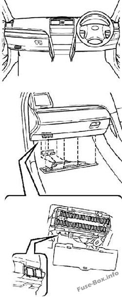
Passenger Compartment Fuse box
Passenger Compartment Fuse box
Fuse box location
Fuse box diagram
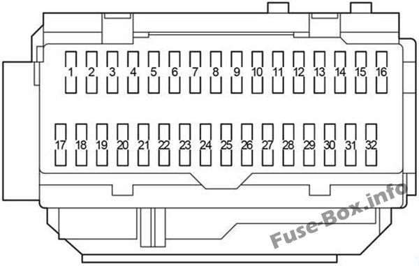
Assignment of the fuses in the Passenger Compartment
| № | Name | Amp | Circuit |
|---|---|---|---|
| 1 | RR DOOR RH | 25 | Rear right power window |
| 2 | RR DOOR LH | 25 | Rear left power window |
| 3 | – | – | – |
| 4 | FR FOG | 15 | Front fog lights |
| 5 | OBD | 7.5 | On-board diagnosis system |
| 6 | ECU-B NO.2 | 7.5 | Power window, driving position memory system |
| 7 | STOP | 10 | Stop lights, high mounted stoplight, shift lock control system, multiport fuel injection system / sequential multiport fuel injection system, anti-lock brake system, vehicle stability control system, traction control system, brake assist system |
| 8 | TI&TE | 30 | Driving position memory system |
| 9 | – | – | – |
| 10 | AM1 | 7.5 | Starting system, multiport fuel injection system / sequential multiport fuel injection system |
| 11 | A/C | 7.5 | Air conditioning system |
| 12 | PWR | 25 | Power windows |
| 13 | DOOR NO.2 | 25 | Main body ECU |
| 14 | S/ROOF | 30 | Electric moon roof |
| 15 | TAIL | 15 | Tail lights, licence plate lights, parking lights, front fog lights, auto headlight levelling system |
| 16 | PANEL | 7.5 | Emergency flashers, air conditioning system, audio system, clock, glove box light, instrument panel lights, steering switches, navigation system, automatic transmission, rear electric sun shade |
| 17 | ECU IG NO.1 | 10 | Main body ECU, electric moon roof, electric cooling fans, windshield wipers and washer, multi-information display, clock, Toyota parking assist-sensor, driving position memory system, auto antiglare inside rear view mirror, charging system, vehicle stability control system, smart entry and start system, rear view monitor system |
| 18 | ECU IG NO.2 | 7.5 | Anti-lock brake system, vehicle stability control system, traction control system, brake assist system, shift lock control system, cruise control system, automatic transmission |
| 19 | A/C NO.2 | 10 | Air conditioning system, rear window defogger |
| 20 | WASH | 10 | Windshield wipers and washers |
| 21 | – | – | – |
| 22 | GAUGE NO.1 | 10 | Emergency flashers, back-up lights, charging system, navigation system, rear electric sun shade |
| 23 | WIP | 25 | Windshield wipers and washer |
| 24 | H-LP LVL | 7.5 | Auto headlight levelling system |
| 25 | TRAILER | 20 | Trailer wiring module |
| INJ | 15 | Multiport fuel injection system / sequential multiport fuel injection system, starting system | |
| 26 | IGN | 10 | Multiport fuel injection system / sequential multiport fuel injection system, SRS airbag system, smart entry and start system, steering lock system, stop lights, electronic throttle control system |
| 27 | GAUGE NO.2 | 7.5 | Gauges and meters, multi-information display, clock |
| 28 | ECU-ACC | 7.5 | Clock, main body ECU, shift lock control system, outside rear view mirrors, smart entry and start system, multi-information display |
| 29 | CIG | 20 | Cigarette lighter |
| 30 | PWR OUTLET | 20 | Power outlet |
| 31 | RADIO NO.2 | 7.5 | Audio system, navigation system |
| 32 | MIR HTR | 10 | Outside rear view mirror defoggers |
Assignment of the fuses in the Passenger Compartment
| № | Name | Amp | Circuit |
|---|---|---|---|
| 1 | P/SEAT | 30 | Power seats, driving position memory system |
| 2 | POWER | 30 | Power windows, driving position memory system |
| Relay | |||
| R1 | Fog Lights | ||
| R2 | Tail Lights | ||
| R3 | Accessory Relay | ||
| R4 | Power Window | ||
| R5 | Ignition (IG1) |
Fuse Box in the Engine Compartment
Fuse Box in the Engine Compartment
Fuse box location
The fuse box is located in the engine compartment (left-side)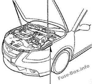
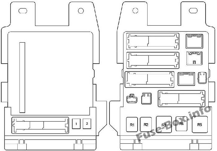
Fuse box diagram
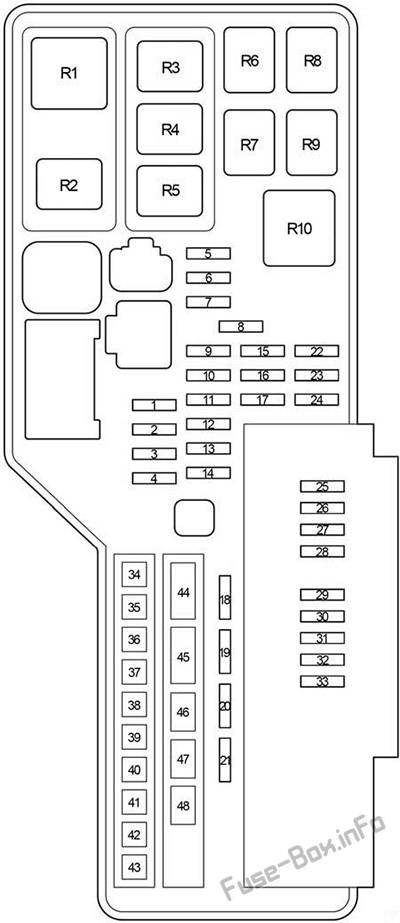
Assignment of the fuses in the Engine Compartment
| № | Name | Amp | Circuit |
|---|---|---|---|
| 1 | – | – | – |
| 2 | – | – | – |
| 3 | – | – | – |
| 4 | – | – | – |
| 5 | AM 2 | 7.5 | Starting system |
| 6 | ALT-S | 7.5 | Charging system |
| 7 | MAYDAY/TEL | 7.5 | Toyota Link system |
| 8 | – | – | – |
| 9 | – | – | – |
| 10 | E-ACM | 10 | Engine active controlled mounting |
| 11 | ETCS | 10 | Electronic throttle control system |
| 12 | HAZ | 15 | Emergency flashers |
| 13 | IG2 | 20 | Multiport fuel injection system / sequential multiport fuel injection system, starting system, “GAUGE NO.2” and “IGN” fuses |
| 14 | STR LOCK | 20 | Steering lock system |
| 15 | DOME | 10 | Gauges and meters, vanity lights, boot light, ignition switch light, door courtesy lights, interior light, personal lights, clock, smart entry and start system, side turn signal lights |
| 16 | ECU-B NO.1 | 10 | Main body ECU, vehicle stability control system, wireless remote control system, multiinformation display, driving position memory system, windshield wipers, rear view monitor system |
| 17 | RADIO NO.1 | 15 | Audio system, navigation system |
| 18 | DOOR NO. | 25 | Main body ECU |
| 19 | – | – | – |
| 20 | AMP | 25 | Audio system, navigation system |
| 21 | EFI MAIN | 30 | Multiport fuel injection system / sequential multiport fuel injection system, automatic transmission, “EFI NO.2” and “EFI NO.3” fuses |
| 22 | – | – | – |
| 23 | EFI NO.3 | 10 | Multiport fuel injection system / sequential multiport fuel injection system |
| 24 | EFI NO.2 | 15 | Multiport fuel injection system / sequential multiport fuel injection system |
| 25 | S-HORN | 7.5 | Horn |
| 26 | A/F | 20 | Multiport fuel injection system / sequential multiport fuel injection system |
| 27 | MPX-B | 10 | Gauges and meters |
| 28 | EFI NO.1 | 10 | Multiport fuel injection system / sequential multiport fuel injection system, smart entry and start system, automatic transmission |
| 29 | HORN | 10 | Horns |
| 30 | H-LP (RL) | 15 | Right-hand headlight (low beam), headlight levelling system |
| 31 | H-LP (LL) | 15 | Left-hand headlight (low beam) |
| 32 | H-LP(RH) | 15 | Right-hand headlight (high beam) |
| 33 | H-LP (LH) | 15 | Left-hand headlight (high beam) |
| 34 | HTR | 50 | Air conditioning system |
| 35 | ABS NO.1 | 50 | Anti-lock brake system, vehicle stability control system, traction control system, brake assist system |
| 36 | FAN MAIN | 50 | Electric cooling fans |
| 37 | ABS NO.2 | 30 | Anti-lock brake system, vehicle stability control system, traction control system, brake assist system |
| 38 | RR DEF | 50 | Rear window defogger, “MIR HTR” fuse |
| 39 | – | – | – |
| 40 | H-LP CLN | 30 | No circuit |
| 41 | – | – | – |
| 42 | – | – | – |
| 43 | – | – | – |
| 44 | ALT | 120 | “AM2” “ALT-S”, “E-ACM”, “ETCS”, “HAZ”, ’TG2″ “STR LOCK”, “DOME”, “ECU-B NO.1”, “RADIO NO.1”, “EFI MAIN”, “DOOR NO.1”, “EFI NO.3”, “EFI NO.2”, “S-HORN”, “A/F HTR”, “MPX-B”, “EFI NO.1”, “HORN”, “H-LP(RL)”, “H-LP(LL)”, “H-LP(RH)”, “H-LP(LH)”, “HTR”, “ABS NO.1”, “ABS NO.2”, “RR DEF”, “FAN MAIN”, “CDS FAN”, “RDI FAN” and “ST/AM2” fuses |
| 45 | – | – | – |
| 46 | – | – | – |
| 47 | – | – | – |
| 48 | ST/AM2 | 30 | Starting system |
| Relay | |||
| R1 | – | ||
| R2 | – | ||
| R3 | – | ||
| R4 | – | ||
| R5 | Electric cooling fan | ||
| R6 | Starter (ST) | ||
| R7 | Ignition (IG) | ||
| R8 | Air conditioner compressor clutch (MG CLT) | ||
| R9 | Starter (ST CUT) | ||
| R10 | Rear window defogger |


