Fuse Layout Skoda Fabia 2007-2014
Contents
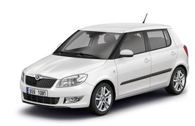
Cigar lighter (power outlet) fuse in the Skoda Fabia is the fuse #47 in the Instrument panel fuse box.
Table of Contents
Color coding of fuses
Color coding of fuses
| Colour | Maximum amperage |
|---|---|
| light brown | 5 |
| brown | 7,5 |
| red | 10 |
| blue | 15 |
| yellow | 20 |
| white | 25 |
| green | 30 |
Fuses in the dash panel
Fuses in the dash panel
Fuse box location
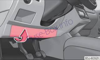
The fuse box is located behind the cover below the steering wheel.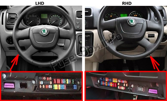
Fuse box diagram
For vehicles with left-hand steering
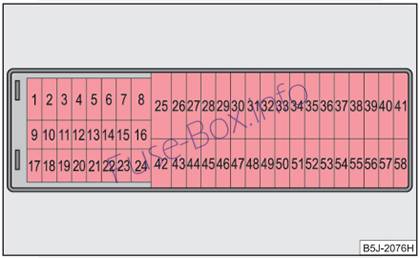
For vehicles with right-hand steering
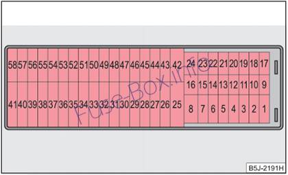
Fuses assignment
| No. | Power consumer | Amperes |
|---|---|---|
| 1 | Not assigned | |
| 2 | START-STOP | 5 |
| 3 | Instrument duster, headlamp beam adjustment | 7,5 |
| 4 | ABS control unit | 5 |
| 5 | Petrol engine: Cruise control system | 5 |
| 6 | Reversing light (manual gearbox) | 10 |
| 7 | Ignition | 15 |
| 7 | Engine control unit automatic gearbox | 7,5 |
| 8 | Brake pedal switch, coolant fan | 5 |
| 9 | Operating controls for the heating, control unit for air conditioning system, parking aid, control unit for cornering lights, coolant fan | 5 |
| 10 | Air conditioning (Only valid for some countries) | 7,5 |
| 11 | Mirror adjustment | 5 |
| 12 | Control unit for trailer detection | 5 |
| 13 | Control unit for automatic gearbox | 5 |
| 14 | Motor for halogen projector headlights with cornering light function | 10 |
| 15 | Navigation PDA | 5 |
| 16 | Electrohydraulic power steering | 5 |
| 17 | START-STOP-radio | 10 |
| Daylight driving lights | 7,5 | |
| 18 | Mirror heater | 5 |
| 19 | S-contact | 5 |
| 20 | Engine control unit | 5 |
| 20 | Engine control unit | 7,5 |
| 20 | Fuel pump relay | 15 |
| 20 | Fuel pump control unit | 15 |
| 21 | Reversing light, fog lights with the function “CORNER” | 10 |
| 22 | Operating controls for the heating, control unit for air conditioning system, parking aid, mobile phone, instrument cluster, steering angle sender, ESP, vehicle voltage control unit multifunction steering wheel | 7,5 |
| 23 | Interior lighting, storage compartment and luggage compartment, side lights | 15 |
| 24 | Central control unit of the vehicle | 5 |
| 25 | Seat heaters | 20 |
| 26 | Rear window wiper | 10 |
| 27 | Not assigned | |
| 28 | Petrol engine: AKF valve, petrol engine: Control flap | 10 |
| 29 | Injection, water pump | 10 |
| 30 | Fuel pump | 15 |
| 30 | Ignition | 20 |
| 30 | Cruise control system, operation of PTC relay | 5 |
| 31 | Lambda probe | 10 |
| 32 | High pressure pump, pressure valve | 15 |
| 33 | Engine control unit | 30/15 |
| 34 | Engine control unit | 15 |
| 34 | Vacuum pump | 20 |
| 35 | Power supply of ignition lock | 5 |
| 36 | Main beam light | 15 |
| 37 | Rear fog light | 7,5 |
| 38 | Fog lights | 10 |
| 39 | Blower | 30 |
| 40 | Heatable windscreen washing nozzles, windscreen cleaning system | 15 |
| 41 | Not assigned | |
| 42 | Rear window heater | 25 |
| 43 | Horn | 20 |
| 44 | Front window wiper | 20 |
| 45 | Central control unit for convenience system | 25/10 |
| 46 | Anti-theft alarm system | 15 |
| 47 | Cigarette lighter, power socket in the luggage compartment (If the engine is switched off already one electrical component which is connected can discharge the battery.) |
15 |
| 48 | ABS, START-STOP – DC/DC converter ESP | 15 |
| 49 | Turn signal lights, brake lights | 15 |
| 50 | START-STOP – DC/DC converter infotainment | 30 |
| 50 | Radio | 10 |
| 51 | Electrical power window (front and rear) – left side | 25 |
| 52 | Electrical power window (front and rear) – right side | 25 |
| 53 | Parking light-left side | 5 |
| 53 | Electric sliding/tilting roof | 25 |
| 54 | START-STOP – instrument cluster | 5 |
| 54 | Anti-theft alarm system | 15 |
| 55 | Control unit for automatic gearbox DSG | 30 |
| 56 | Headlight cleaning system | 25 |
| 56 | Parking light – right side | 5 |
| 57 | Left low beam, headlight range adjustment | 15 |
| 58 | Low beam on the right | 15 |
Fuses at the battery (manual gearbox, automatic gearbox DSG)
Fuses at the battery (manual gearbox, automatic gearbox DSG)
Fuse box location
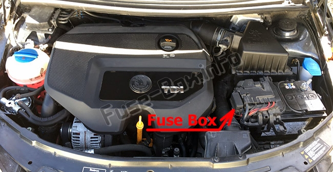
The battery: Fuse cover

Fuse box diagram
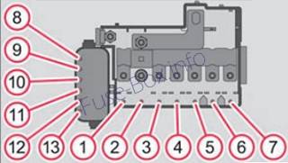
| No. | Power consumer | Amperes |
|---|---|---|
| 1 | Dynamo | 175 |
| 2 | Not assigned | |
| 3 | Interior | 80 |
| 4 | Electrical auxiliary heating system | 60 |
| 5 | Interior | 40 |
| 6 | Glow plugs, coolant fan | 50 |
| 7 | Electrohydraulic power steering | 50 |
| 8 | ABS or TCS or ESP | 25 |
| 9 | The radiator fan | 30 |
| 10 | The radiator fan | 5 |
| 11 | ABS or TCS or ESP | 40 |
| 12 | Central control unit | 5 |
| 13 | Automatic gearbox | 5 |
| 13 | Electrical auxiliary heating system | 40 |
Fuses at the battery (automatic gearbox)
Fuses at the battery (automatic gearbox)
Fuse box location
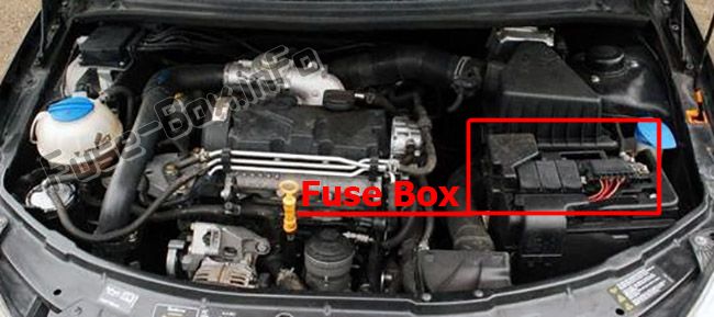
The battery: Open the positive terminal cover / fuse cover
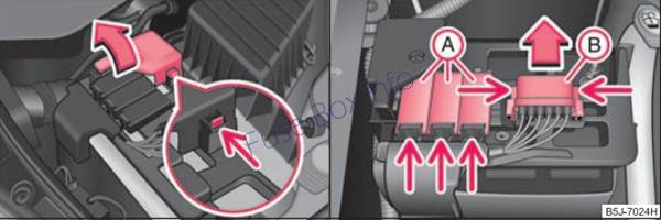
Fuse box diagram
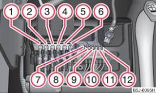
| No. | Power consumer | Amperes |
|---|---|---|
| 1 | Dynamo | 175 |
| 2 | Interior | 80 |
| 3 | Electrical auxiliary heating system | 60 |
| 4 | ESP | 40 |
| 5 | Electrohydraulic power steering | 50 |
| 6 | Glow plugs | 50 |
| 7 | ESP | 25 |
| 8 | The radiator fan | 30 |
| 9 | Air conditioning system | 5 |
| 10 | ABS | 40 |
| 11 | Central control unit | 5 |
| 12 | Automatic gearbox | 5 |
| 12 | Electrical auxiliary heating system | 40 |


