

Fuse Layout Renault Modus 2005-2012
Contents
Cigar lighter (power outlet) fuse in the Renault Modus is the fuse F9 in the Instrument panel fuse box.
Table of Contents
Fuse box #1 in the passenger compartment
Fuse box location
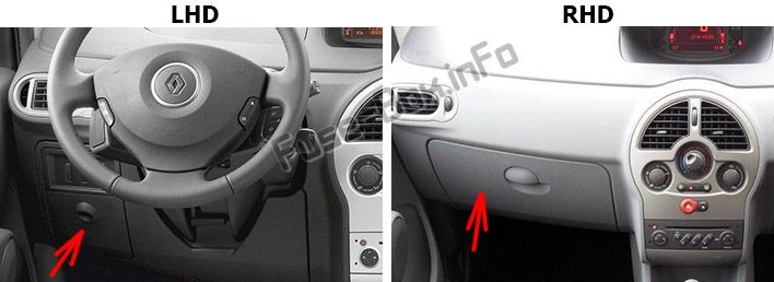
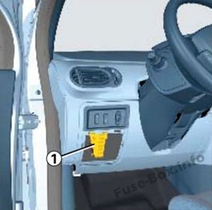
Left-hand drive vehicles:
The fuse box is located on the left of the steering wheel behind the cover.
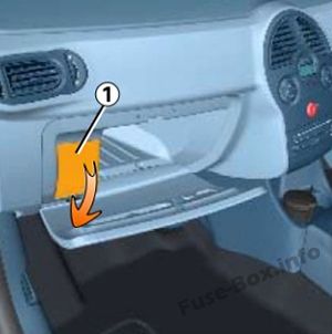
Right-hand drive vehicles:
The fuse box is located in the glove compartment behind the cover.
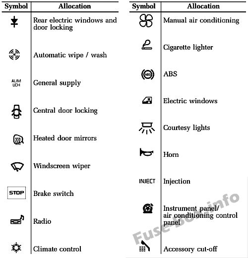
Fuse box diagram
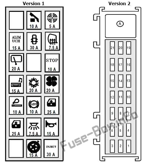
Assignment of the fuses in the Passenger Compartment Fuse Box 1
| № | A | Description |
|---|---|---|
| F1 | 30 | UCH |
| F2 | 15 | Instrument panel – air conditioning control unit – fuse and relay box |
| F3 | – | Not in use |
| F4 | 15 | Main electromagnetic horn – diagnostic socket – driving school control monitor |
| F5 | 7.5 | UCH |
| F6 | 25 | Driver’s electric window motor – child safety lock control |
| F7 | 25 | Driver’s dual front electric window control |
| F8 | 10 | ABS computer – electronic stability program – cluster sensor |
| F9 | 10 | First row cigarette lighter |
| F10 | 20 | Passenger compartment fan assembly 1 |
| F11 | 20 | Passenger compartment fan assembly 1 |
| F12 | 15 | Air conditioning control unit – climate control control panel – radio – steering wheel controls – radio telephone central unit – front and rear bi-directional washer pump – power supply fuse board – passenger compartment fuse and relay box 2 – driver’s heated seat – passenger heated seat – self-supplied alarm siren |
| F13 | 10 | Passenger compartment fuse and relay box 2 – brake switch |
| F14 | – | Not in use |
| F15 | 20 | Rear screen wiper motor |
| F16 | 7.5 | Driver’s electric door mirror – passenger electric door mirror |
| F17 | 30 | UCH |
| F18 | 15 | UCH – engine immobiliser |
| F19 | 5 | Rain and light sensor – passenger compartment fan sensor |
| F20 | 10 | Consumer cut-out – instrument panel – radio – radio telephone central unit – electric door mirror switch – self-supplied alarm siren – pressure monitoring system central unit pneumatic |
| Diode | ||
| F21 | – | Child safety lock control |
| Relay | ||
| A | 50 | + Accessories feed |
Assignment of the fuses in the passenger compartment (2008)
Fuse Box #2 in the passenger compartment
This unit is attached to the instrument panel crossbar, underneath the passenger airbag.
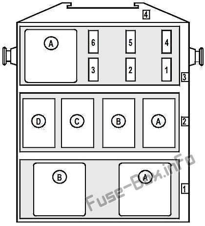
Assignment of the fuses in the Passenger Compartment Fuse Box 2
| № | A | Description |
|---|---|---|
| Fuse and relay board (row 3) | ||
| F1 | 20 | Driver’s and passenger door deadlocking relay feed (relay A on plate 1531, row 2) on right-hand drive version |
| F2 | 20 | Driver’s heated seat – passenger heated seat |
| F3 | 15 | Sunroof central unit |
| F4 | 25 | Driver’s dual rear electric window control supply relay (relay A on plate 1531 row 1) |
| F5 | – | Not in use |
| F6 | – | Not in use |
| A | – | Not in use (Relay) |
| Relay board (row 2) | ||
| A | 20 | Driver’s and passenger door central locking (on right-hand drive version) |
| B | 20 | Brake lights |
| C | – | Not in use |
| D | – | Not in use |
| Relay plate (row 1) | ||
| A | 50 | Driver’s dual rear electric window control |
| B | 50 | Driver’s left and right-hand rear electric window control |
Relay panel
This panel is located under the dashboard on the left-hand side of the passenger compartment fan assembly
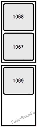
| № | A | Description |
|---|---|---|
| 1067 | 35 | Auxiliary heater 1 |
| 1068 | 50 | Auxiliary heater 2 |
| 1069 | 50 | Auxiliary heater 3 (1500 Watt version) |
Fuse box in the Engine Compartment
This unit is located in the engine compartment, behind the left-hand headlight.
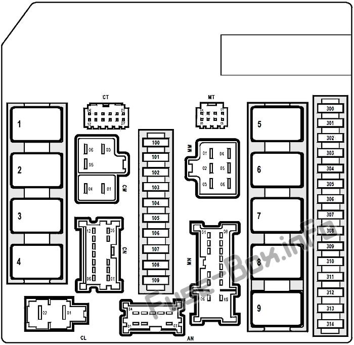
Assignment of the fuses and relays in the Engine Compartment Fuse Box
| № | A | Description |
|---|---|---|
| 100 | 25 | ABS computer or Electronic Stability Program |
| 101 | – | Not in use |
| 102 | 10 | Right-hand main beam headlights |
| 103 | 10 | Left-hand main beam headlights |
| 104 | 10 | Right-hand side light – rear right-hand light – right-hand heated seat control – electronic stability programme on/off button – rear right-hand electric window control – climate control control panel -air conditioning control unit – central door locking switch – CD changer – speed limiter on/off control – on right-hand drive version: – driver’s dual rear electric window control – child safety lock control – driver’s dual front electric window control – electric door mirror control – passenger electric window control |
| 105 | 10 | Left-hand side light – rear left-hand light – left-hand heated seat control – right-hand license plate light – left-hand license plate light – first row cigarette lighter – headlight height adjustment control – rear left-hand electric window control – radio – gear lever display – poor traction control – on left-hand drive version: – driver’s dual rear electric window control – child safety lock control – driver’s dual front electric window control – electric door mirror control – passenger electric window control |
| 106 | 15 | Shift pattern control – UPC – auxiliary heater relay – power assisted steering / gear lever display diagnostic socket – hands-free kit – radio telephone central unit – driving school monitor control – central unit Tyre pressure monitor / central unit discharge bulbs |
| 107 | 20 | Windscreen wiper motor |
| 108 | 15 | Right-hand headlight / right-hand headlight adjustment motor |
| 109 | 15 | Left-hand headlight / left-hand headlight adjustment motor |
| 300 | 10 | Air conditioning compressor clutch |
| 301 | – | Not in use |
| 302 | 25 | Starter motor solenoid |
| 303 | 20 | + Protected automatic clutch computer battery feed |
| 304 | – | Not in use |
| 305 | 15 | Heated rear screen |
| 306 | 15 | Headlight washer supply relay (relay A and B on board 777) |
| 307 | 5 | + Automatic gearbox computer after ignition feed |
| 308 | – | Not in use |
| 309 | 10 | Reversing lights |
| 310 | 20 | Ignition coils feed |
| 311 | 20 | + Protected injection computer battery feed |
| 312 | 10 | + Airbag and pretensioner after ignition feed |
| 313 | 10 | + Injection computer after ignition feed |
| 314 | 20 | Front left and right-hand fog lights |
| Relays | ||
| 1 | – | Heated rear screen |
| 2 | – | Injection locking |
| 3 | – | Dipped beam headlights |
| 4 | – | Front headlights |
| 5 | – | Starter |
| 6 | – | Not in use |
| 7 | – | Engine cooling fan high-speed |
| 8 | – | Engine cooling fan low-speed |
| 9 | – | + After ignition feed |
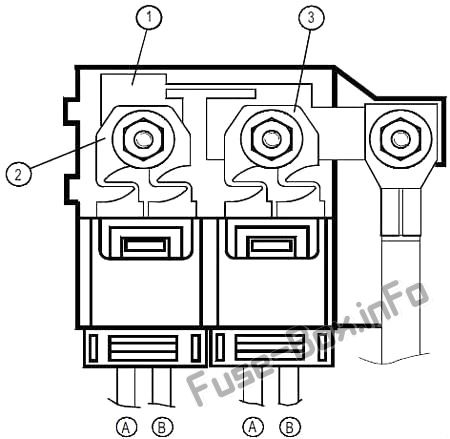
Fuses on the positive battery terminal
| № | A | Description |
|---|---|---|
| Main fuse (mark 1) | ||
| – | 350 | Fuse inputs F2 to F8 feed on power supply fuse board – starter – alternator – supply to fuses marked 2 and 3 on protected battery unit |
| Fuse marked 2 (BLUE connector) | ||
| A | 70 | Fuse inputs F17 and F18 feed passenger compartment fuse and relay unit – UPC |
| B | 60 | Electric power assisted steering system |
| Fuse marked 3 (GREEN connector) | ||
| A | 70 | Fuse inputs F1, F3, F5 feed and accessories relays on passenger compartment fuse and relay unit |
| B | 60 | UPC |
Power feed fuse board
This unit is located on the front side of the battery tray.
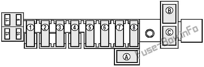
Power feed fuse board
| No. | A | Description |
|---|---|---|
| F1 | 30 | Injection central unit supply relay on K9K or 764 engine (R5 relay on optional relay unit) |
| F2 | 30 | Sequential gearbox electric pump unit relay on D4F engine with sequential gearbox Preheating unite on K9K engines |
| F3 | 30 | Air conditioning and cooling fan assembly on K9K and D4F engines with sequential gearbox |
| F4 | 30 | Air conditioning and cooling fan assembly on K4M / K4J / D4F engines with manual gearbox
Sequential gearbox electric pump unit relay on K9K engines with sequential gearbox |
| F5 | 50 | F12 fuse input feed – fuses F1, F2, F3, F4 input feeds on passenger compartment fuse and relay box 2 |
| F6 | 80 | Passenger compartment auxiliary heater |
| F7 | 60 | Passenger compartment auxiliary heater |
| F8 | 50 | ABS computer |
| F9 | – | Not in use |
| F10 | – | Not in use |
| F11 | – | Not in use |
| F12 | 10 | Left-hand headlights supply relay >on discharge bulb version |
| Relays | ||
| A | 20 | Headlight washer pump |
| B | 20 | Headlight washer pump relay |
| C | 20 | Left-hand headlights on discharge bulb version |
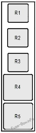
Optional relay panel
This unit is attached to the front of the battery tray.
| № | A | Description |
|---|---|---|
| R1 | – | Not in use |
| R2 | – | Not in use |
| R3 | – | Not in use |
| R4 | 50 | Sequential gearbox electric pump unit |
| R5 | 50 | Injection central unit on K9K 764 engine |


