

Fuse Layout Nissan Note 2004-2013
Contents

Cigar lighter (power outlet) fuses in the Nissan Note are the fuses #18 (Rear Power Point) and #20 (Front Power Point – Cigarette Lighter) in the Instrument panel fuse box.
Table of Contents
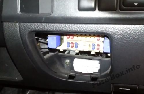
Fuse box location
Passenger compartment overview
Left-hand drive vehicles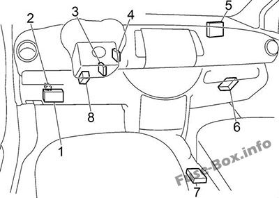
Right-hand drive vehicles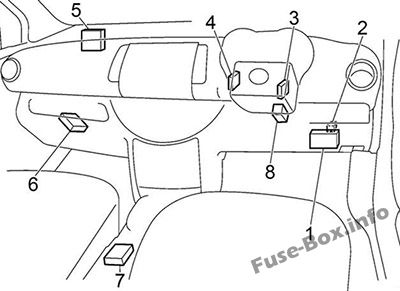
1. Fuse Box
2. Door Lock Relay (with Intelligent Key System)
3. Nissan Anti-Theft System (NATS) Antenna Amplifier
4. Intelligent Key Unit (with Intelligent Key System)
5. Body Control Module (BCM)
6. Transmission Control Module
7. Air Bag Diagnosis Sensor Unit
8. ESP Control Unit
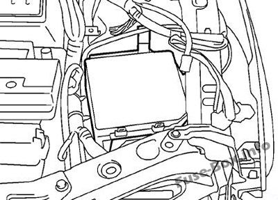
Engine Compartment overview
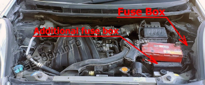
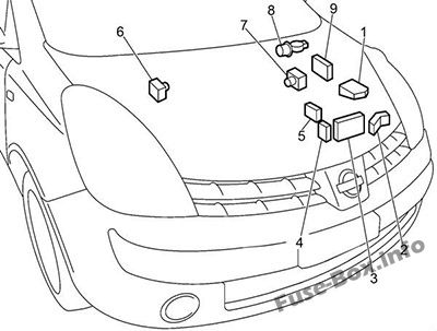
1. Fuse Box (IPDM E/R)
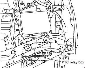
2. PTC Relay Box
3. Additional Fuse Box
4. K9K: Fusible Link Box
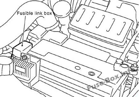
5. Fusible Link Holder (on the battery)
6. LHD: ABS Actuator and Electric Unit
7. RHD: ABS Actuator and Electric Unit
8. Wiper Motor
9. Engine Control Module (ECM)
Fuse box diagrams
Passenger compartment
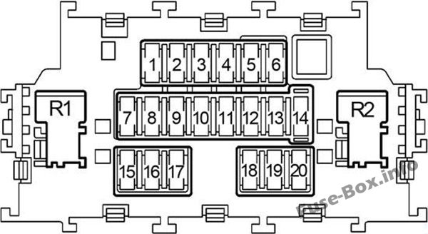
Assignment of the fuses in the passenger compartment
| № | Amp | Circuit |
|---|---|---|
| 1 | 10 | Supplemental Restraint System |
| 2 | 10 | Electric Controlled Power Steering System Ignition Relay Fuel Pump Relay Nissan Anti-Theft System Intelligent Key System Body Control Module (BCM) |
| 3 | 10 | Cluster Warning Lamps Illumination Warning Chime Charging System |
| 4 | 15 | Front Washer Rear Washer |
| 5 | 10 | Mirror Defogger |
| 6 | 10 | Audio Intelligent Key System Nissan Anti-Theft System Door Mirror |
| 7 | 10 | Body Control Module (BCM) |
| 8 | 10 | Central Locking Multi-remote Control System Intelligent Key System After Market Alarm – Prewire Warning Chime Nissan Anti-Theft System |
| 9 | 10 | Stop Lamp Brake Switch Anti-lock Brake System Electronic Stability Program System Warning Lamps Intelligent Key System |
| 10 | – | – |
| 11 | – | – |
| 12 | 10 | Interior Lamp Multi-remote Control System Illumination Vanity Mirror and Trunk Room Lamps Rain Sensor Warning Chime |
| 13 | – | – |
| 14 | 10 | Panel Illumination OBD II (Board Computer Diagnostics) Intelligent Key System Turn Signal and Hazard Warning Lamps |
| 15 | 15 | Air Conditioner |
| 16 | 10 | PTC Heater |
| 17 | 15 | Air Conditioner |
| 18 | 15 | Rear Power Point |
| 19 | 10 | Heated Seat |
| 20 | 15 | Front Power Point (Cigarette Lighter) |
| Relay | ||
| R1 | Blower motor | |
| R2 | Accessory |
Engine compartment
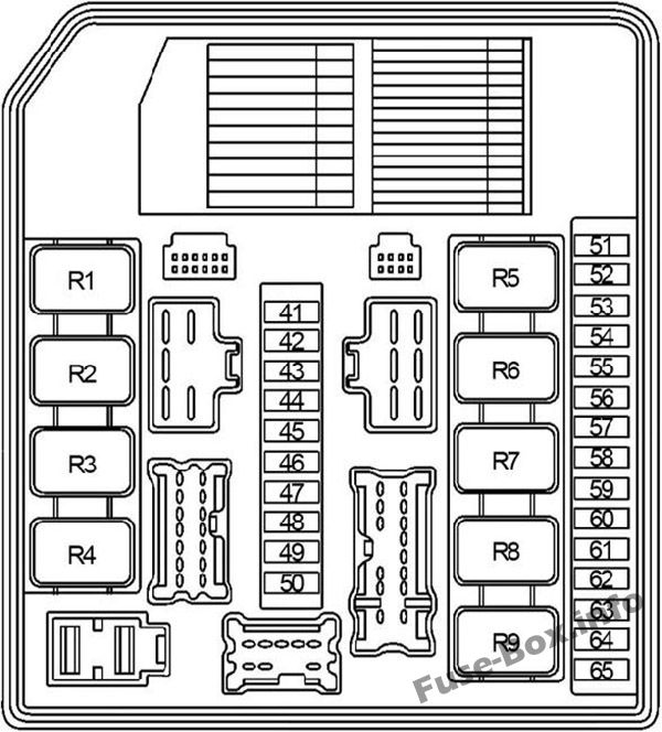
Assignment of the fuses in the engine compartment
| № | Amp | Circuit |
|---|---|---|
| 41 | – | – |
| 42 | – | – |
| 43 | 10 | Right-Hand Headlights (High Beam) Daytime Light System Auto Light Control |
| 44 | 10 | Left-Hand Headlights (High Beam) Daytime Light System Auto Light Control |
| 45 | 10 | Tail Light Parking Light Auto Light Control Illumination |
| 46 | 10 | Tail Light Parking Light Auto Light Control Headlamp Illumination |
| 47 | – | – |
| 48 | 20 | Front Wiper and Washer System (With Rain Sensor) |
| 49 | 15 | Left-Hand Headlights (Low Beam) Daytime Light System Auto Light Control |
| 50 | 15 | Right-Hand Headlights (Low Beam) Daytime Light System Auto Light Control |
| 51 | 10 | Air Conditioner |
| 52 | – | – |
| 53 | – | – |
| 54 | – | – |
| 55 | 15 | Rear Window Defogger “5” fuse |
| 56 | 15 | Rear Window Defogger “5” fuse |
| 57 | 15 | CR, HR: Fuel Pump Relay |
| 58 | 10 | Vehicle Speed Sensor A/T (Revolution Sensor) A/T Fluid Temperature Sensor and TCM Power Supply Main Power Supply and Ground Circuit Turbine Revolution Sensor |
| 59 | 10 | Anti-lock Brake System Electronic Stability Program System |
| 60 | 10 | Park/Neutral Position Switch NON-detective Items Starting System Back-up Lamp A/T Indicator Lamp Rear Wiper and Washer |
| 61 | 20 | CR, HR: Throttle Control Motor Relay |
| 62 | 20 | Engine Control Module Relay Main Power Supply and Ground Circuit Mass Air Flow Sensor Crankshaft Position Sensor (CKPS) Camshaft Position Sensor (PHASE) EVAP Canister Purge Volume Control Solenoid Valve Ignition System Intake Valve Timing Control Solenoid Valve After Market Alarm – Prewire Fuel Injector Camshaft Position Sensor Fuel Flow Actuator Turbocharger Boost Control Solenoid Valve Brake Switch ECM Power Supply For Back-up (CR engine) |
| 63 | 10 | CR, HR: Front Heated Oxygen Sensor Rear Heated Oxygen Sensor Fuel Injection System Function, |
| 64 | 10 | CR, HR: Fuel Injection System Function Fuel Injector |
| 65 | 20 | Front Fog Lamp |
| Relay | ||
| R1 | Rear Window Defogger | |
| R2 | Engine Control Module (ECM) | |
| R3 | Headlamp Low | |
| R4 | Front Fog Lamp | |
| R5 | Starter | |
| R6 | – | |
| R7 | Cooling Fan (High) | |
| R8 | Cooling Fan (Low) | |
| R9 | Ignition |
Additional Fuse Box
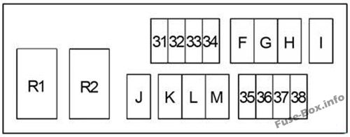
Assignment of the fuses in the Additional Fuse Box
| № | Amp | Circuit |
|---|---|---|
| 31 | – | – |
| 32 | – | – |
| 33 | – | – |
| 34 | 15 | Audio System |
| 35 | 10 | Horn |
| 36 | 10 | CR, HR: Charging System |
| 37 | 10 | Daytime Light System |
| 38 | – | – |
| F | 40 | Anti-lock Brake System Electronic Stability Program System |
| G | 40 | Cooling Fan Low Relay Cooling Fan High Relay |
| H | 40 | Ignition Switch |
| I | 40 | PTC Heater |
| J | 40 | Power Window Body Control Module (BCM) |
| K | 30 | Anti-lock Brake System Electronic Stability Program System |
| L | 30 | Headlamp Washer |
| M | 60 | Electric Controlled Power Steering System |
| Relay | ||
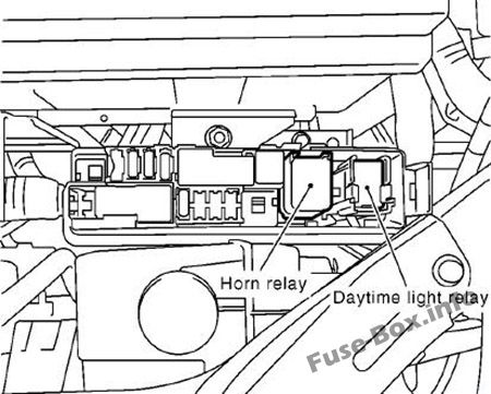
| R1 | Daytime Light | |
| R2 | Horn |
Fusible Link Box (K9K engine)
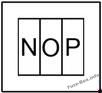
| № | Amp | Circuit |
|---|---|---|
| N | 80 | PTC Heater |
| O | 60 | Quick Glow System |
| P | 80 | PTC Heater |
Fusible Link Block
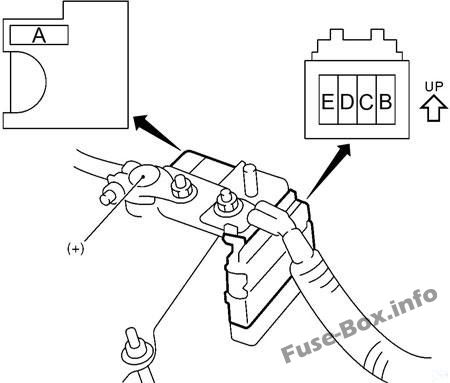
Fusible Link Block
| № | Amp | Circuit |
|---|---|---|
| A | 80 | CR: Charging System, Starting System “B”, “C” fuses |
| A | 140 | HR: Charging System, Starting System “B”, “C” fuses |
| A | 250 | K9K: Charging System “B”, “C”, “N”, “0”, “P” fuses |
| B | 80 | CR, K9K: “35”, “36”, “37”, “38”, “F”, “G”, “H”, “I”, “J”, “K”, “L”, “M” fuses |
| B | 100 | HR: “35”, “36”, “37”, “38”, “F”, “G”, “H”, “I”, “J”, “K”, “L”, “M” fuses |
| C | 80 | Headlamp High RH Relay (“43” fuse) Headlamp High LH Relay (“44” fuse) Tail Lamp Relay (“45”, “46” fuses) Headlamp Low Relay (“49”, “50” fuses) Front Fog Lamp Relay (“65” fuse) “48”, “51” fuses |
| D | 60 | Ignition Relay (Front Wiper Main Relay Front Wiper Hi/Lo Relay “57” (CR, HR), “58”, “59”, “60”, “63” (CR, HR), “64” (CR, HR) fuses), Fuel Pump Relay (CR, HR), “55”, “56”, “61”, “62” fuses |
| E | 80 | Accessory Relay (“18”, “19”, “20” fuses) Blower Motor Relay (“15”, “16”, “17” fuses) “1”, “2”, “3”, “4”, “5”, “6”, “7”, “8”, “9”, “12”, “14” fuses |


