


Fuse Layout Nissan Quest 2004-2009
Contents
Cigar lighter (power outlet) fuses in the Nissan Quest are the fuses #5 (Front Power Socket 2, Rear Power Socket – 2nd Row) and #21 (Front Power Socket 1, Rear Power Socket – Cargo) in the Instrument panel fuse box.
Table of Contents
Instrument Panel Fuse Box
Instrument Panel Fuse Box
Fuse box location
The fuse box is located behind the storage compartment to the left of the steering wheel.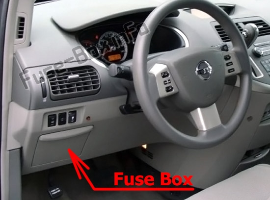
Fuse box diagram
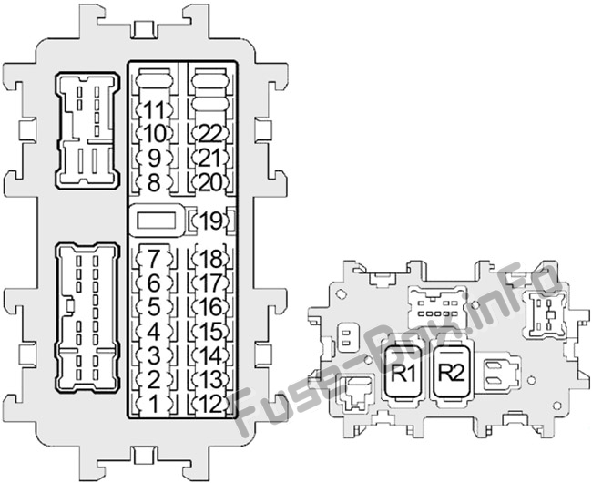
Assignment of the fuses and relays in the instrument panel
| № | Amp | Description |
|---|---|---|
| 1 | 10 | Pedal Adjusting Control Unit, Stop Lamp Switch |
| 2 | 10 | Front Blower Motor Relay, Front Air Control |
| 3 | 15 | Body Control Module (BCM), Auto Anti-Dazzling Inside Mirror |
| 4 | 10 | Audio, AV Switch, Display Unit, Display Control Unit, Navi Control Unit, DVD Player, Satellite Radio Tuner, Body Control Module (BCM) |
| 5 | 15 | Front Power Socket 2, Rear Power Socket (2nd Row) |
| 6 | 10 | Door Mirror Remote Control Switch |
| 7 | – | Not Used |
| 8 | 10 | Door Mirror |
| 9 | 10 | Driver Seat Control Unit, Diode 1 |
| 10 | 15 | Rear Blower Motor |
| 11 | 15 | Rear Blower Motor |
| 12 | 10 | Automatic Speed Control Device (ASCD) Brake Switch, Data Link Connector, Combination Meter, Heated Seat Relay, Park Neutral Position Switch, Display Unit, Steering Angle Sensor, Display Control Unit, Navi Control Unit, Back Door Control Unit, Sliding Door Control Unit RH/LH, Sonar Control Unit, Daytime Running Lights, Hands Free Telephone |
| 13 | 10 | Air Bag Diagnosis Sensor Unit, Occupant Classification System Control Unit |
| 14 | 10 | Combination Meter, Park Neutral Position Switch, Auto Dimming Inside Mirror |
| 15 | – | Not Used |
| 16 | 10 | Injectors, Body Control Module (BCM), Engine Control Module (ECM) |
| 17 | 10 | Navi Control Unit, Back Door Control Unit, Sliding Door Control Unit RH/LH, Driver Seat Control Unit, Seat Memory Switch, Auto Drive Positioner Control Unit |
| 18 | 15 | Subwoofer |
| 19 | 15 | Transmission Control Module (TCM), A/V Switch, Display Unit, Steering Angle Sensor, Combination Meter, Front Electronic Controlled Engine Mount, Display Control Unit, Key Switch, Front Air Control |
| 20 | 10 | Stop Lamp Switch |
| 21 | 15 | Front Power Socket 1, Rear Power Socket (Cargo) |
| 22 | 15 | Fuel Lid Opener Relay, DVD Player |
| Relays | ||
| R1 | Blower | |
| R2 | Accessory |
Fuse Boxes in the Engine Compartment
Fuse Boxes in the Engine Compartment
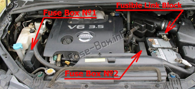
Fuse box location
Fuse box #1 diagram
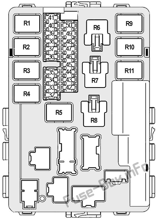
Assignment of the fuses and relays in the Engine Compartment Fuse Box #1
| № | Amp | Description |
|---|---|---|
| 32 | 20 | Rear Window Defogger Relay |
| 33 | 10 | Air Conditioner Relay |
| 34 | 15 | IPDM E/R CPU |
| 35 | 15 | Engine Control Module (ECM), ECM Relay, NATS Antenna Amplifier |
| 36 | 15 | Headlamp Low (right), Diode 3 |
| 37 | 20 | Rear Window Defogger Relay |
| 38 | 10 | Headlamp High (left), Daytime Running Lights Control Unit |
| 39 | 30 | Front Wiper Relay |
| 40 | 10 | Headlamp High (right), Daytime Running Lights Relay, Diode 3 |
| 41 | 15 | Tail Lamp Relay, Cornering Lamp Relay, IPDM E/R CPU |
| 42 | 10 | Heater Pump Relay |
| 43 | 15 | Front Fog Lamp Relay |
| 44 | 15 | Throttle Control Motor Relay |
| 45 | 15 | Headlamp Low (left), Daytime Running Lights |
| 46 | 15 | Air Flow Sensor, Heater Oxygen Sensor |
| 47 | 10 | Combination Switch (Front Wiper and Washer, Rear Wiper and Washer) |
| 48 | 10 | Transmission Control Module (TCM), Revolution Sensor, Turbine Revolution Sensor, A/T PV IGN Relay |
| 49 | 10 | ABS |
| 50 | 15 | Fuel Pump Relay |
| Relays | ||
| R1 | Engine Control Module | |
| R2 | Headlamp High | |
| R3 | Headlamp Low | |
| R4 | Starter | |
| R5 | Ignition | |
| R6 | Cooling Fan (No.1) | |
| R7 | Cooling Fan (No.3) | |
| R8 | Cooling Fan (No.2) | |
| R9 | Throttle Control Motor | |
| R10 | Fuel Pump | |
| R11 | Front Fog Lamp |
Fuse box #2 diagram
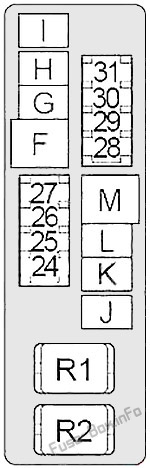
Assignment of the fuses and relays in the Engine Compartment Fuse Box #2
| № | Amp | Description |
|---|---|---|
| 24 | 20 | Trailer Tow Power Supply |
| 25 | 15 | Horn Relay |
| 26 | 10 | Generator |
| 27 | 15 | Heated Seat Relay |
| 28 | 20 | Front Blower Motor Relay |
| 29 | 15 | Daytime Running Lights |
| 30 | 20 | Front Blower Motor Relay |
| 31 | 20 | Audio, BOSE Amplifier, Satellite Radio Tuner |
| F | 40 | ABS |
| G | 40 | Cooling Fan Relay 2 |
| H | 40 | Cooling Fan Relay 1, Cooling Fan Relay 3 |
| I | 40 | Circuit Breaker 1 (Slide Door Auto Closure System, Power Seat) |
| J | 50 | Body Control Module (BCM) |
| K | 40 | Ignition Switch |
| L | 40 | ABS |
| M | 40 | Circuit Breaker 2 (Adjustable Pedal System, Automatic Drive Positioner, Slide Door Auto Closure System, Power Seat) |
| Relays | ||
| R1 | Horn | |
| R2 | Front Blower Motor |
Fusible Link Block (Main Fuses)
It is located on the positive terminal of the battery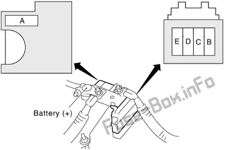
Fusible Link Block
| № | Amp | Description |
|---|---|---|
| A | 140 | Generator, Fuses D, E |
| B | 80 | Accessory Relay (Fuses 4, 5, 6), Rear Blower Motor Relay (Fuses 10, 11), Fuses 3, 17, 18, 19, 20, 21, 22 |
| C | 60 | Ignition Relay (Fuses 42, 46, 47, 48, 49, 50), Fuses 33, 34, 35, 37 |
| D | 80 | Headlamp High Relay (Fuses 38, 40), Headlamp Low Relay (Fuses 36, 45), Fuses 32, 39, 41, 43, 44 |
| E | 100 | Fuses F, G, H, J, 24, 25, 26, 27 |


