

Fuse Layout Nissan Maxima 1999-2003
Contents

Cigar lighter (power outlet) fuses in the Nissan Maxima are the fuses #16 and #22 in the Instrument panel fuse box.
Table of Contents
Passenger Compartment Fuse Box
Passenger Compartment Fuse Box
Fuse box location
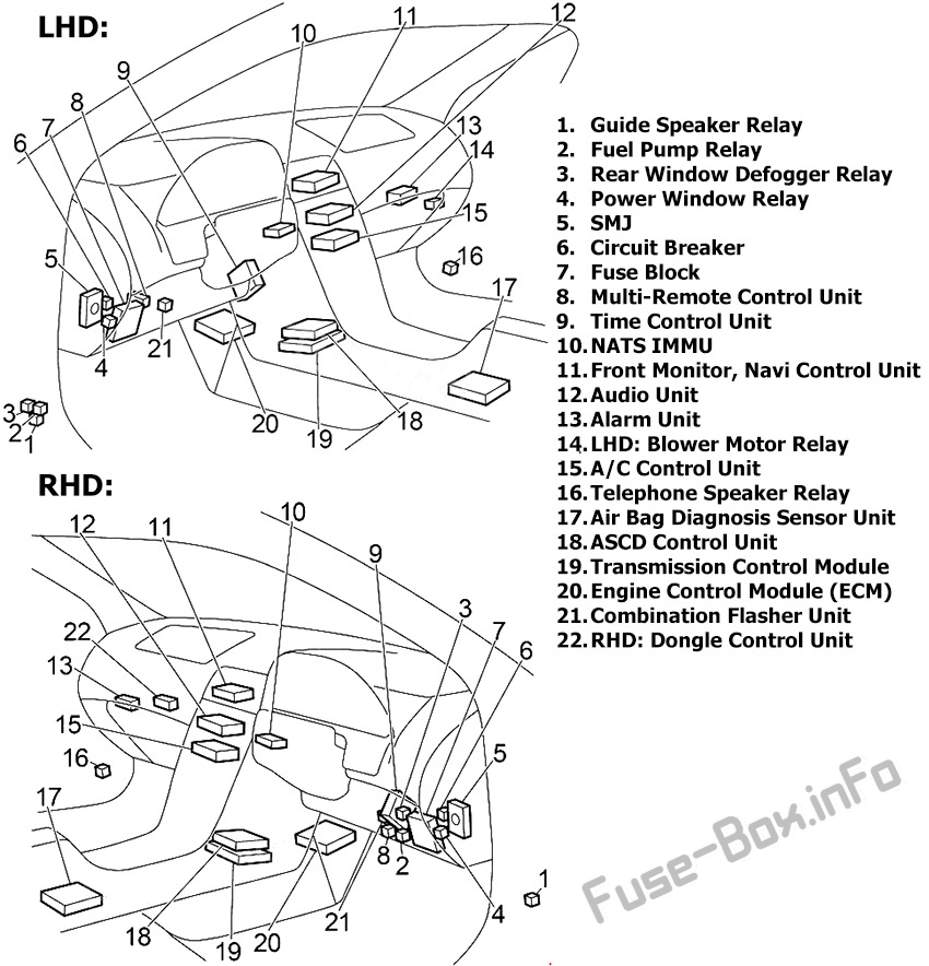
The fuse box is located behind the cover on the driver’s side of the instrument panel.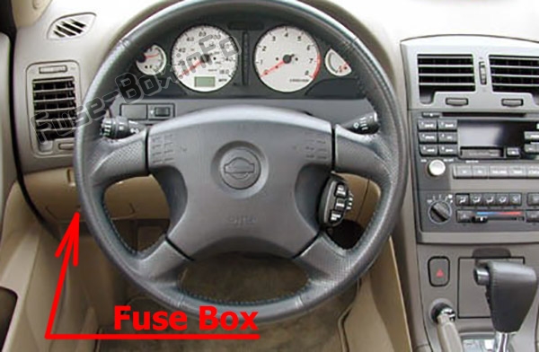
Fuse Box Diagram
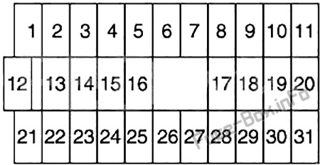
Assignment of fuses in the instrument panel
| № | Amp Rating | Description |
|---|---|---|
| 1 | 10 | Steering Wheel Receiver Control Switch, Audio Unit, CD Player, CD Changer, Woofer, Telephone Speaker Relay, Antenna, Telephone Control Unit, Front Monitor |
| 2 | 15 | Stop Lamp Switch (Rear Combination Lamp LH/RH, High-Mounted Stop Lamp), ASCD Control Unit, ABS, Transmission Control Unit |
| 3 | 15 | Trunk Lid Opener, Fuel Lid Opener, Trunk Lid Opener Relay (RHD) |
| 4 | – | Not Used |
| 5 | 15 | Hazard Switch (Combination Flasher Unit), Multi-Remote Control Unit |
| 6 | 15 | Front Fog Lamp Relay |
| 7 | 20 | Rear Window Defogger Relay |
| 8 | 15 | Heated Oxygen Sensor |
| 9 | 10 | Heated Seat Switch LH/RH |
| 10 | 10 | Daytime Light Control Unit, Headlamp Aiming Control Unit, Door Switch, Headlamp Washer Control Unit, Height Sensor Rear LH/RH, Clearance Lamp LH/RH, License Lamp LH/RH, Rear Combination Lamp LH/RH, Power Window Switch (Illumination), Power Window Relay, Time Control Unit, Rear Window Defogger Relay, Auto Anti-Dazzling Inside Mirror, ASCD Brake Switch, ASCD Clutch Switch, ASCD Control Unit, Park/Neutral Position Relay, Data Link Connector, Multi-Remote Control Unit, Alarm Unit, Navi |
| 11 | 10 | Transmission Control Unit, Revolution Sensor, A/T Mode Switch |
| 12 | 10 | Key Switch, Time Control Unit, Combination Meter, Clock, Alarm Unit, Security Indicator, NATS Immu, Navi, Data Link Connector, A/C Auto Amplifier, Transmission Control Unit |
| 13 | 10 | Interior Lamp, Front Step Lamp, Door Switch, Time Control Unit, Ignition Key Hole Illumination, Spot Lamp, Vanity Mirror Lamp LH/RH (Illumination), Trunk Room Lamp/Switch, Rear Window Defogger Relay (Door Mirror) |
| 14 | 10 | Combination Meter, Clock, Door Mirror Remote Control Switch, Navi Control Unit, Front Monitor |
| 15 | – | Not Used |
| 16 | 15 | Power Socket |
| 17 | 10 | Injector, Fuel Pump Relay (ECM) |
| 18 | 10 | Air Bag Diagnosis Sensor Unit |
| 19 | 10 | A/C Auto Amplifier, A/C Relay, A/C Control Unit, Air Mix Door Motor |
| 20 | 15 | Park/Neutral Position Relay (Park/Neutral Position Switch), NATS IMMU, EVAP Canister Purge Valve Volume Control Solenoid Valve, Swirl Control Valve Control Solenoid Valve, Cooling Fan Relay (1, 2, 3), Variable Induction Air Control System, ASCD |
| 21 | 10 | Daytime Light Control Unit, Engine Control Module |
| 22 | 15 | Cigarette Lighter |
| 23 | – | Not Used |
| 24 | – | Not Used |
| 25 | 20 | Front Wiper Motor, Front Washer Motor, Front Wiper Switch |
| 26 | 10 | Hazard Switch (Combination Flasher Unit) |
| 27 | – | Not Used |
| 28 | – | Not Used |
| 29 | 15 | Fuel Pump Relay (Fuel Pump and Fuel Level Sensor, Condenser) |
| 30 | 10 | Combination Meter, Daytime Light Control Unit, Alternator, Park/Neutral Position Switch (Back-Up Lamp), Door Switch, ASCD Brake Switch, ASCD Clutch Switch, ASCD Control Unit, Park/Neutral Position Relay |
| 31 | 10 | ABS |
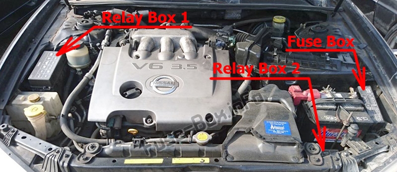
Engine Compartment Fuse Box
Engine Compartment Fuse Box
Fuse box location
Fuse Box Diagram
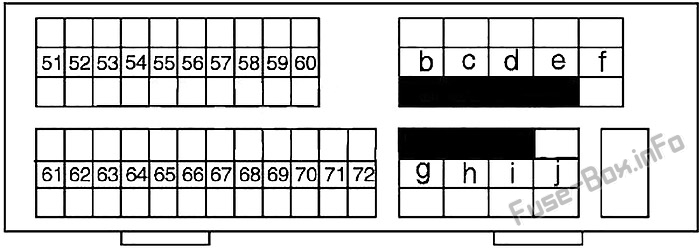
Assignment of fuses in the engine compartment
| № | Amp Rating | Description |
|---|---|---|
| 51 | 15 | Blower Motor Relay |
| 52 | 15 | Blower Motor Relay |
| 53 | – | Not Used |
| 54 | 20 | Headlamp (Left) Relay, Headlamp (Left Low Beam), Diode |
| 55 | 20 | Headlamp (Right) Relay, Headlamp (Right Low Beam), Diode |
| 56 | 15 | Audio Unit, CD Player, CD Changer, Telephone Control Unit, Navi Control Unit, Front Monitor |
| 57 | 10 | Horn Relay |
| 58 | 15 | IACV-ACC Valve, ECM Relay (Condenser, Ignition Coil) |
| 59 | 15 | ECM Relay, NATS IMMU, Throtlle Position Switch, Crankshaft Position Sensor, Front Electronic Controlled Engine Mount, Rear Electronic Controlled Engine Mount |
| 60 | 10 | Headlamp Switch, Daytime Light Control Unit, Headlamp Aiming Motor LH/RH, Fog Lamp Switch, Navi Control Unit, Headlamp Washer Control Unit, Time Control Unit, Illunination Control Switch (Combination Meter, Audio Unit, CD Player, Cigarette Lighter, Headlamp Washer Switch, Glove Box Lamp, Hazard Switch, Navi Control Unit, Door Mirror Remote Control Switch, Clock, Headlamp Aiming Switch, A/T Device, A/C Control Unit, A/C Amplifier (Auto A/C), Ashtray) |
| 61 | – | Not Used |
| 62 | – | Not Used |
| 63 | – | Not Used |
| 64 | – | Not Used |
| 65 | 10 | Rear Fog Lamp Relay, Rear Fog Indicator |
| 66 | 10 | A/C Relay |
| 67 | 15 | Woofer |
| 68 | 15 | Headlamp (Left), Headlamp Switch, High Beam Indicator, Dimmer Relay, Diode, Daytime Light Control Unit, Headlamp (Left) Relay (Xenon) |
| 69 | 15 | Headlamp (Right), High Beam Indicator, Diode, Daytime Light Control Unit, Headlamp (Right) Relay (Xenon), Rear Fog Lamp Switch |
| 70 | 10 | Charging System |
| 71 | – | Not Used |
| 72 | – | Not Used |
| B | 80 | Accessory Relay (Fuse: “22”), Ignition Relay (Fuse: “8”, “9”, “10”, “11”), Blower Motor Relay (Fuse: “14”, “16”), Fuse: “12”, “13”, |
| C | 40 | Ignition Switch |
| D | 40 | ABS |
| E | 40 | ABS |
| F | 30 | Headlamp Washer Motor (Headlamp Washer Control Unit) |
| G | 40 | Cooling Fan Relay 1 (Low), Cooling Fan Relay 2 (High) |
| H | 40 | Cooling Fan Relay 3 |
| I | 40 | Circuit Breaker (Time Control Unit, Door Lock, Power Window Relay, Power Window Main Switch, Sunroof Motor, Power Seat) |
| J | 80 | Ignition Relay (Fuse: “25”, “26”, “29”, “30”, “31”), Fuse: “2”, “3”, “5”, “6”, “7” |
Relay Box #1
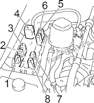
| № | Relay |
|---|---|
| 1 | Air Conditioner |
| 2 | Horn |
| 3 | Xenon: Right Headlamp; except Xenon: Dimmer |
| 4 | Headlamp Washer Control Unit |
| 5 | Front Fog Lamp |
| 6 | Rear Fog Lamp |
| 7 | Xenon: Left Headlamp |
| 8 | Theft Warning |
Relay Box #2
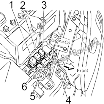
| № | Relay |
|---|---|
| 1 | Cooling Fan Relay 3 |
| 2 | Park/Neutral Position |
| 3 | RHD: Blower Motor |
| 4 | Cooling Fan Relay 1 |
| 5 | Cooling Fan Relay 2 |
| 6 | Engine Control Module (ECM) |


