Fuse Layout Nissan Almera II 2000-2006
Contents
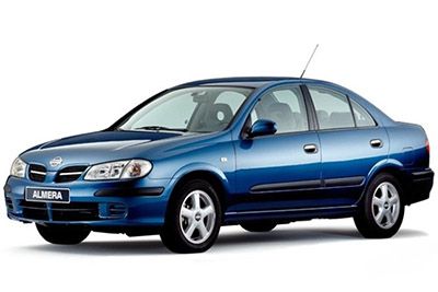
Cigar lighter (power outlet) fuses in the Nissan Almera II are the fuses #3 (Socket) and #22 (Cigarette lighter) in the Instrument panel fuse box.
Table of Contents
Fuse box location
Fuse box location

Passenger compartment Fuse box
Passenger compartment Fuse box
The fuse box is located on the left side of the dashboard, behind the storage compartment.

Fuse box diagram
Front side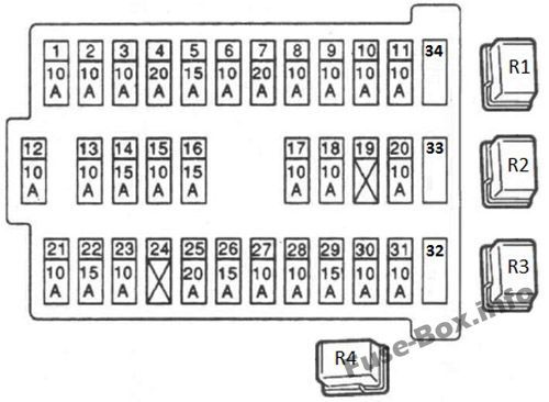
Rear side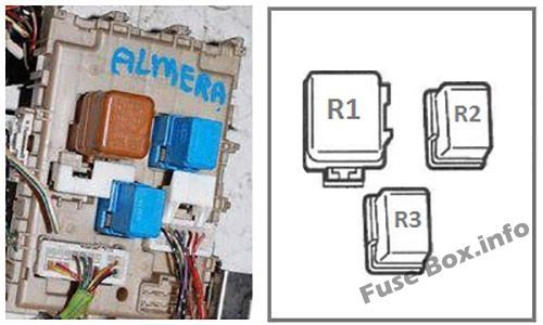
Assignment of the fuses and relay in the passenger compartment
| № | Amp | Component |
|---|---|---|
| 1 | 10A | Mirrors |
| 2 | 10A | Brake lights |
| 3 | 15A | Socket |
| 4 | 7,5A | For additional electronic equipment |
| 5 | 15A | Alarms and indicators |
| 6 | 10A | Additional electric equipment |
| 7 | 20A | Rear window defogger |
| 8 | 10A | Oxygen Sensor |
| 9 | 10A | Additional electronic equipment |
| 10 | 10A | Electronic equipment |
| 11 | 10A | Automatic Transmission |
| 12 | 10A | ECU (turn signals, backlight and main power to the instrument panel, panel lighting) |
| 13 | 10A | Interior lamp |
| 14 | 15A | Interior fan (heater / air conditioning) |
| 15 | 10A | Air Conditioner |
| 16 | 15A | Fan (heater / air conditioner) |
| 17 | 10A | Fuel Injection System |
| 18 | 10A | Airbags |
| 19 | 20A | Additional electric equipment |
| 20 | 10A | Engine module |
| 21 | 10A | Start signal |
| 22 | 15A | Cigarette lighter |
| 23 | – | Not used |
| 24 | 20A | Additional electric equipment |
| 25 | 20A | Windshield wipers |
| 26 | 7,5A | Additional electric equipment |
| 27 | 15A | Front and/or rear window washer (on the stalk switch) |
| 28 | 15A | Rear window washer |
| 29 | 15A | Fuel pump |
| 30 | 10A | Speedometer, tachometer, temperature and fuel level indicators |
| 31 | 10A | ABS |
| 32 | 10A | Reserve |
| 33 | 15A | Reserve |
| 34 | 20A | Reserve |
| Front side relay | ||
| R1 | Headlight relay | |
| R2 | Throttle Control Relays | |
| R3 | Power windows relay | |
| R4 | Rear fog light relay | |
| Rear side relay | ||
| R1 | Ignition relay | |
| R2 | The supercharger relay | |
| R3 | Additional equipment relay (electrical accessories) |
Fuse Boxes in the Engine Compartment
Fuse Boxes in the Engine Compartment
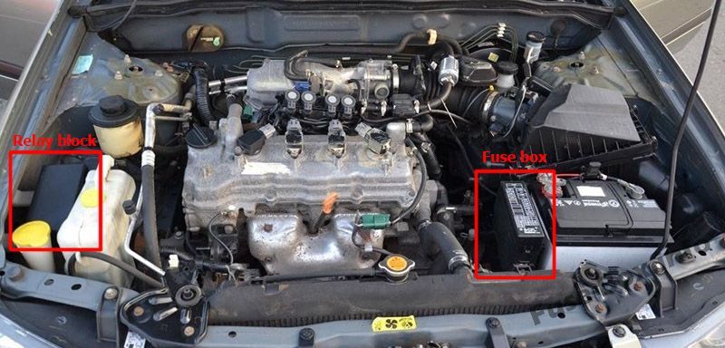
Fuse box diagram
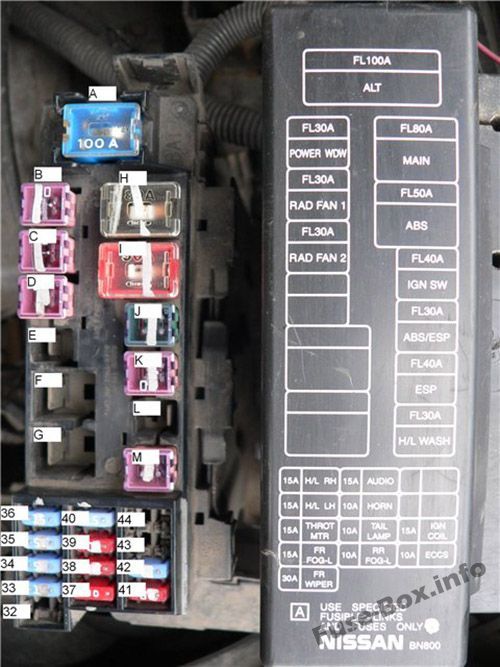
Assignment of the fuses in the Engine Compartment Fuse Box
| № | Amp | Component |
|---|---|---|
| A | 100A | Generator (battery charging) |
| B | 40A | Power windows |
| C | 40A | Cooling fans |
| D | 40A | Cooling fans |
| E | 30A | For diesel engines |
| F | 60A | For diesel engines |
| G | 80A | For diesel engines |
| H | 80A | Main power supply, grounding circuit |
| I | 50A | ABS |
| J | 30A | To the battery ignition switch |
| K | 30A | ABS/ESP |
| L | 30A | ESP |
| M | 30A | Headlight washer |
| 32 | 20A | Rear window washer |
| 33 | 15A | Fog lights |
| 34 | 15A | Electric drive and throttle actuator relay |
| 35 | 15A | Headlamps, daytime running light |
| 36 | 15A | Headlamps, daytime running light |
| 37 | 10A | Rear fog light |
| 38 | 10A | Parking lights, license plate lighting |
| 39 | 10A | Horn, battery charging |
| 40 | 15A | Audio, navigation, LCD display |
| 41 | 10A | Engine management system |
| 42 | 10A | Ignition coil |
| 43 | 15A | Not used |
| 44 | 10A | Not used |
Relay block
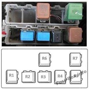
| № | Relay |
|---|---|
| R1 | Cooling fan relay 3 (25221E) |
| R2 | Front fog lights (25224QA) |
| R3 | Air conditioner relay E6 (25224D) |
| R4 | Horn relay (25620) |
| R5 | Cooling fan relay (25224J) |
| R6 | Lights (25224A) |
| R7 | Starter (25224G) |


