

Fuse Layout Infiniti M45 2003-2004
Contents

Table of Contents
Passenger Compartment Fuse Boxes
Passenger Compartment Fuse Boxes
Fuse Box Location
There are two fuse boxes that are located on the right and left under the dashboard (open the lids to access the fuses).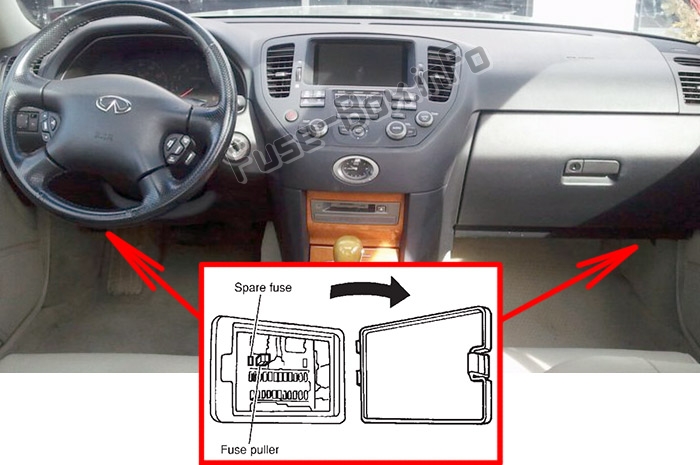
Fuse Box Diagram (Driver side)
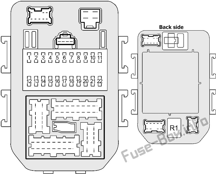
Assignment of fuses in the passenger compartment (Driver side)
| № | Ampere Rating | Description |
|---|---|---|
| 1 | 10 | Body Control Module (BCM), Intelligent Cruise Control (ICC) Warning Chime, ICC Sensor, ICC Unit, ICC Brake Hold Relay, AV and Navi Control Unit, NATS IMMU, Auto Anti-Dazzling Inside Mirror, Homelink Universal Transceiver, Headlamp Battery Saver Control Unit, Rear Window Defogger Relay, Dual Mode Muffler Control Unit, Door Mirror, Climate Controlled Seat Relay, Climate Controlled Seat Control Unit (Driver/Passenger Side) |
| 2 | 10 | A/C Auto Amplifier, ECV Solenoid Valve (A/C Compressor) |
| 3 | 10 | Body Control Module (BCM), Trunk Lid Opener Relay |
| 4 | 10 | Door Mirror Remote Control Switch, Handset, Door Mirror Defogger Relay |
| 5 | 10 | Combination Flasher Unit |
| 6 | 10 | Data Link Connector, Combination Meter, A/C Auto Amplifier, Handset, Low Tire Pressure Warning Control Unit, Security Indicator Lamp, Body Control Module (BCM), NATS IMMU, Steering Lock Control Unit, Warning Chime, Headlamp Battery Saver Control Unit, Clock |
| 7 | 10 | VDC/TCS/ABS Control Unit, Power Steering Control Unit |
| 8 | 10 | Driver/Passenger Door Mirror Control Unit, Auto Anti-Dazzling Inside Mirror, Homelink Universal Transceiver, Ignition Key Hole Illumination, Map Lamps, Console Lamp, Rear Personal Lamps, Front Step Lamps, Rear Step Lamps, Vanity Mirror Lamps, Trunk Room Lamp, Seat Memory Switch |
| 9 | 10 | Combination Meter, Back-Up Lamp Relay, Alternator |
| 10 | 20 | Rear Window Defogger Relay, Door Mirror Defogger Relay |
| 11 | 20 | Rear Window Defogger Relay, Door Mirror Defogger Relay |
| 12 | 10 | Automatic Speed Control Device (ASCD) Control Unit, ASCD Brake Switch, Shift Lock Control Unit |
| 13 | 15 | Fuel Injectors, Engine Control Module (ECM), Fuel Pump Relay |
| 14 | 10 | Starting System, Engine Control Module (ECM), Body Control Module (BCM), Daytime Light Control Unit |
| 15 | 10 | Trunk Closure Control Unit, Trunk Lid Opener Actuator, Fuel Lid Opener Actuator |
| 16 | 10 | Heated Oxygen Sensors |
| 17 | 15 | Stop Lamp Switch, Intelligent Cruise Control (ICC) Brake Hold Relay, A/T Device, VDC/TCS/ABS Control Unit |
| 18 | 10 | Heated Oxygen Sensors |
| 19 | 10 | Not Used |
| 20 | 10 | Air Bag Diagnosis Sensor Unit |
| 21 | 10 | Audio Unit, BOSE Speaker Amplifier, CD Auto Changer, Satellite Radio Receiver, AV and Navi Control Unit, Display, Multifunction Switch, Voice Activated Control Module, Low Tire Pressure Warning Control Unit, A/C Auto Amplifier, Blower Motor Relay, Body Control Module (BCM), Combination Meter |
| 22 | 15 | Combination Flasher Unit |
| R1 | Accessory Relay |
Fuse Box Diagram (Passenger side)
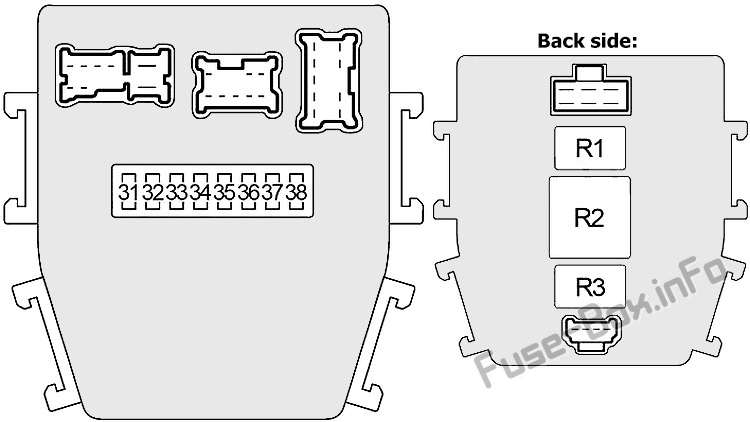
Assignment of fuses in the passenger compartment (Passenger side)
| № | Ampere Rating | Description |
|---|---|---|
| 31 | 15 | Blower Motor |
| 32 | 10 | Key Switch and Key Lock Solenoid, Engine Control Module (ECM) Relay (Intake Valve Timing Control Position Sensor, Mass Air Flow Sensor, Crankshaft Position Sensor, Camshaft Position sensor), Transmission Control Module (TCM), A/T PV IGN Relay, NATS IMMU |
| 33 | 15 | Blower Motor |
| 34 | 20 | Front Wiper Relay, Front Wiper Motor, Front Washer Motor |
| 35 | 10 | Transmission Control Module (TCM), A/T PV IGN Relay |
| 36 | 15 | Fuel Pump Relay |
| 37 | 10 | Handset |
| 38 | – | Not Used |
| R1 | Blower Relay | |
| R2 | Engine Control Module (ECM) Relay | |
| R3 | Fuel Pump Relay |
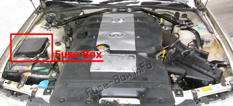
Engine Compartment Fuse Box
Engine Compartment Fuse Box
Fuse Box Location
Fuse Box Diagram
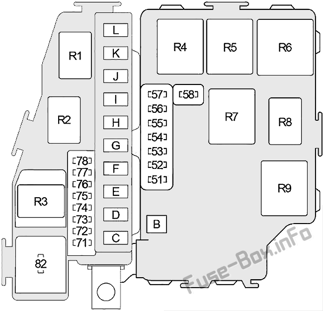
Assignment of fuses in the engine compartment
| № | Ampere Rating | Description |
|---|---|---|
| 51 | 10 | Air Conditioner Relay |
| 52 | 15 | Audio, Satellite Radio Receiver, CD Auto Changer, AV and Navi Control Unit, Display, Voice Activated Control Module |
| 53 | 20 | Engine Control Module (ECM) Relay (Ignition Coils, Condenser, Intake Valve Timing Control Solenoid Valve) |
| 54 | 15 | Tail Lamp Relay (Front/Rear Combination Lamps, Front/Rear Side Marker Lamp, License Lamps, Glove Box Lamp, Illumination Control Switch, Illumination: Cigarete Lighter, Multifunction Switch, VDC Off Switch, Hazard Switch, Audio Unit, CD Auto Changer, A/T Device, Clock, Headlamp Aiming Switch, AV and Navi Control Unit, Climate Controlled Seat Switch, Climate Controlled Seat Level Switch, Ashtrays), Headlamp Aiming Motor LH/RH, Headlamp Battery Saver Control Unit |
| 55 | 20 | Right Headlamp (Low Beam), Headlamp Relay №1 |
| 56 | 15 | Horn Relay, Alternator |
| 57 | 20 | Left Headlamp (Low Beam), Headlamp Relay №1 |
| 58 | 10 | Data Link Connector, EVAP Canister Purge Volume Control Solenoid Valve, EVAP Canister Vent Control Valve, Vacuum Cut Valve Bypass Valve, Variable Intake Air System (VIAS) Control Solenoid Valve |
| 71 | 15 | Climate Controlled Seat Relay |
| 72 | 15 | Climate Controlled Seat Relay |
| 73 | 15 | Headlamp (High Beam), Headlamp Relay №2, Combination Meter, Daytime Light Control Unit |
| 74 | 15 | Throttle Control Motor Relay |
| 75 | 20 | BOSE Speaker Amplifier |
| 76 | 15 | Frong Fog Lamp Relay |
| 77 | 10 | Intelligent Cruise Control (ICC) Unit |
| 78 | 10 | Security Horn Relay |
| 82 | 10 | Daytime Light Control Unit |
| B | 50 | Ignition Relay (Fuses: “1”, “2”, “5”, “7”, “9”, “34”, “35”, “36”, “37”, “82”) |
| C | 50 | Accessory Relay (Fuse: “4”; Circuit Breaker №3 – Cigar Lighter, Front Power Socket), Fuses: “3”, “6”, “8”, “10”, “11”, “15”, “17”, “22” |
| D | – | – |
| E | – | – |
| F | 30 | VDC/TCS/ABS (Solenoid Valve Relay) |
| G | 50 | Ignition Switch |
| H | 40 | Circuit Breaker №1 (Power Window, Door Lock, Driver Door Control Module, Rear LH Door Control Unit, Body Control Module (BCM), Sunroof Motor), Circuit Breaker №2 (Power Window, Door Lock, Passenger Door Control Module, Rear RH Door Control Unit, Driver Seat Control Unit) |
| I | – | – |
| J | – | – |
| K | 50 | VDC/TCS/ABS (Motor Relay) |
| L | 50 | Blower Relay (Fuses: “31”, “33”), Fuse: “32” |
| Relay | ||
| R1 | Front Wiper | |
| R2 | Throttle Control Motor | |
| R3 | Headlamp (№2) | |
| R4 | Headlamp (№1) | |
| R5 | Park/Neutral Position | |
| R6 | Air Conditioner | |
| R7 | Tail Lamp | |
| R8 | Horn | |
| R9 | Ignition |


