

Fuse Layout Chrysler Aspen 2004-2009
Contents

Cigar lighter (power outlet) fuse in the Chrysler Aspen is the fuse F18 in the Interior fuse box.
Table of Contents
Interior fuse box
Interior fuse box
Fuse box location
It is located in the left side kick panel behind a removable cover near the park brake pedal.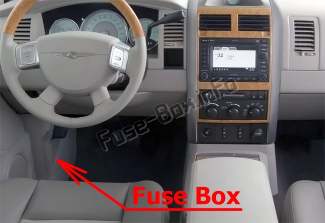
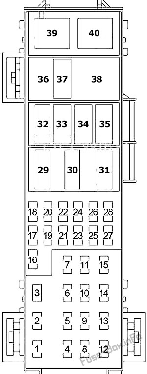
Fuse box diagram
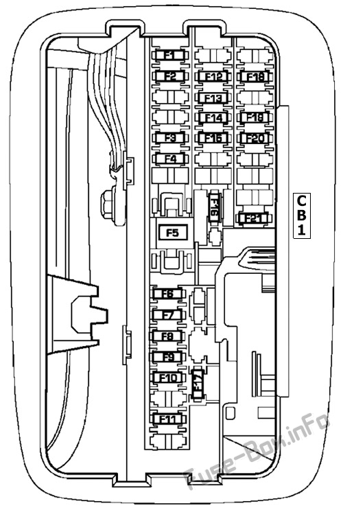
Assignment of fuses in the interior fuse box (2007-2009)
| Cavity | Mini Fuse/Color | Description |
|---|---|---|
| F1 | 15 Amp Blue | Instrument Cluster Battery Feed |
| F2 | 10 Amp Red | Spare |
| F3 | 10 Amp Red | Ignition Run/Start for Next Generation Controller (NGC), Integrated Power Module (IPM), AC Relay and Fuel Pump Relay |
| F4 | 10 Amp Red | Door Node and Non-Memory Power Mirror Switch Battery Feed |
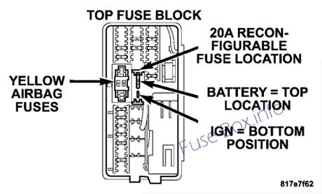
| F5 | (2) 10 Amp Red | Airbags (2 Fuses in Yellow Holder) |
| F6 | 2 Amp Clear | Ignition Run/Start Unlock |
| F7 | 25 Amp Natural | Radio Battery Feed |
| F8 | 10 Amp Red | Ignition Run/Start for Cluster/Transfer Case/Seat Sw. Back lighting |
| F9 | 10 Amp Red | Satellite Digital Audio Receiver (SDAR)/ Digital Video Disc (DVD) Battery Feed |
| F10 | 10 Amp Red | Spare |
| F11 | 10 Amp Red | Heated Mirrors |
| F12 | 20 Amp Yellow | Cluster Battery Feed |
| F13 | 10 Amp Red | Ignition Run HVAC Module/Heated Rear Glass (EBL) Relay |
| F14 | 10 Amp Red | ABS Module Ignition Run |
| F15 | 15 Amp Blue | Battery Feed Blue Tooth, Compass/Trip Computer (CMTC), Sentry Key Diagnostics |
| F16 | 20 Amp Yellow | Reconfigurable Power Outlets |
| F17 | 20 Amp Yellow | Ignition Run / Rear Park Assist / Second Row Heated Seats |
| F18 | 20 Amp Yellow | Cigar Lighter Ignition |
| F19 | 10 Amp Red | Spare Fuse |
| F20 | 15 Amp Blue | Heating & Air Conditioning w/ATC Only Battery Feed |
| F21 | 25 Amp Natural | Amplifier Battery Feed |
| CB1 | 25 Amp Circuit Breaker | Sunroof Motor, Power Window |
Power Distribution Center
Power Distribution Center
Fuse box location
It is located in the left side of the engine compartment.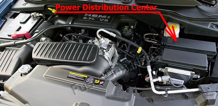
Fuse box diagram
Assignment of fuses in the Power Distribution Center (2007-2009)
| Cavity | Cartridge Fuse / Relay | Mini Fuse | Description |
|---|---|---|---|
| 1 | 30 Amp Pink | Starter | |
| 2 | 30 Amp Pink | Front Wiper | |
| 3 | 40 Amp Green | Brake Batt | |
| 4 | 30 Amp Pink | JB Feed Acc # 2 | |
| 5 | 40 Amp Green | Power Seats | |
| 6 | 30 Amp Pink | Run Remote Relay Feed | |
| 7 | 40 Amp Green | Blower Motor Relay Feed | |
| 8 | 40 Amp Green | JB Feed Acc Delay | |
| 9 | Spare | ||
| 10 | 30 Amp Pink | ASD | |
| 11 | 40 Amp Green | Power Liftgate ( If Equipped) | |
| 12 | 40 Amp Green | JB Feed / Heated Rear Glass (EBL)/ T Case Brake | |
| 13 | 30 Amp Pink | JB Feed RR | |
| 14 | 40 Amp Green | ESP Pump | |
| 15 | 50 Amp Red | JB Feed | |
| 16 | 10 Amp Red | Spare | |
| 17 | Spare | ||
| 18 | 20 Amp Yellow | Fuel Pump | |
| 19 | 20 Amp Yellow | Next Generation Controller (NGC) | |
| 20 | 25 Amp Clear | 115v Power Inverter | |
| 21 | 20 Amp Yellow | ABS Batt | |
| 22 | 20 Amp Yellow | Next Generation Controller (NGC) Batt | |
| 23 | 20 Amp Yellow | Trailer Tow | |
| 24 | 15 Amp Blue | A/C Clutch | |
| 25 | 15 Amp Blue | Stop Lamp Switch | |
| 26 | Spare | ||
| 27 | 20 Amp Yellow | Run/Start Relay Feed | |
| 28 | Spare | ||
| 29 | Relay | Run Start | |
| 30 | Relay | Run Remote | |
| 31 | Spare | ||
| 32 | Relay | Starter | |
| 33 | Relay | Electronic Automatic Transaxle (EATX) | |
| 34 | Relay | AC Clutch | |
| 35 | Relay | Fuel Pump Rly | |
| 36 | Spare | ||
| 37 | Relay | Stop Lamp Switch | |
| 38 | Spare | ||
| 39 | Relay | Blower Motor | |
| 40 | Relay | Auto Shut Down (ASD) Rly |
Integrated Power Module
Integrated Power Module
Fuse box location
An integrated Power Module is located in the left side of the engine compartment.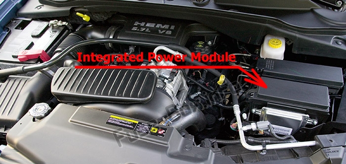
Fuse box diagram
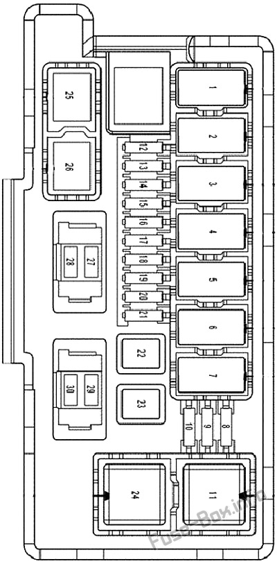
Assignment of fuses in the Integrated Power Module (2007-2009)
| Cavity | Cartridge Fuse / Relay | Mini Fuse | Description |
|---|---|---|---|
| 1 | Relay | Wiper On/Off Rly | |
| 2 | Relay | Wiper Hi/Lo Rly | |
| 3 | Relay | Horn Rly | |
| 4 | Relay | Rear Wiper Rly | |
| 5 | Relay | Lt Trailer-Tow Stop/ Turn Rly | |
| 6 | Relay | Rt Trailer-Tow Stop/ Turn Rly | |
| 7 | Relay | Park Lamps Rly | |
| 8 | 10 Amp Red | Lt Park Lamps | |
| 9 | 10 Amp Red | Trailer-Tow Park Lamps | |
| 10 | 10 Amp Red | Rt Park Lamps | |
| 11 | Relay | Radiator Fan Hi Rly | |
| 12 | 20 Amp Yellow | Front Control Module (FCM) Batt #4 | |
| 13 | 20 Amp Yellow | Front Control Module (FCM) Batt #2 | |
| 14 | 20 Amp Yellow | Adjustable Pedal | |
| 15 | 20 Amp Yellow | Ft Fog Lamps | |
| 16 | 20 Amp Yellow | Horn | |
| 17 | 20 Amp Yellow | Rear Wiper | |
| 18 | 20 Amp Yellow | Front Control Module (FCM) Batt #1 | |
| 19 | 20 Amp Yellow | Lt Trailer-Tow Stop/ Turn | |
| 20 | 20 Amp Yellow | Front Control Module (FCM) Batt #3 | |
| 21 | 20 Amp Yellow | Rt Trailer-Tow Stop/ Turn | |
| 22 | 30 Amp Pink | Front Control Module (FCM) BATT # 5 | |
| 23 | 40 Amp Green | Radiator Fan | |
| 24 | Relay | Radiator Fan Lo Rly | |
| 25 | Relay | Ft Fog Lamps Rly | |
| 26 | Relay | Adjustable Pedal Rly | |
| 27 | 30 Amp Green | Ignition Off Draw (IOD) #1 | |
| 28 | 30 Amp Green | Ignition Off Draw (IOD) #2 | |
| 29 | Spare | ||
| 30 | Spare |


