

Fuse Layout Chrysler Cirrus 1994-2000
Contents

Cigar lighter (power outlet) fuse in the Chrysler Cirrus is the fuse #8 in the Instrument panel fuse box.
Table of Contents
Passenger Compartment Fuse Box
Passenger Compartment Fuse Box
Fuse box location
It is located behind the cover on the driver’s side of the dashboard. Pull the cover straight away from the instrument panel for access.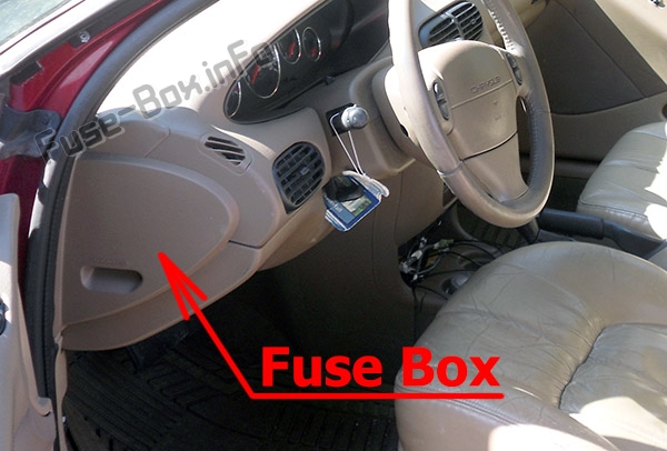
Fuse Box Diagram
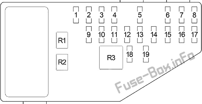
Assignment of fuses in the instrument panel
| № | Amp Rating | Description |
|---|---|---|
| 1 | 30 | Blower Motor |
| 2 | 10 / 20 | Right Headlamp (High Beam), Daytime Running Lamp Module (Convertible – 20A) |
| 3 | 10 / 20 | Left Headlamp (High Beam) (Convertible – 20A) |
| 4 | 15 | Back-Up Lamp (Back-Up Lamp Switch (M/T), Transmission Range Sensor (A/T)), Power Top Relay (Convertible), Daytime Running Lamp Module, Power Door Lock Switch, Power Mirror Switch, Automatic Day/Night Mirror, Steering Proportional Steering Module |
| 5 | 10 | Dome Lamp, Data Link Connector, Power Antenna, Overhead Map Lamp, Trunk Lamp, Traveler, Body Control Module, Radio, Glove Box Lamp, Visor/Vanity Lamp, Universal Garage Door Opener, Automatic Day/Night Mirror, Illuminated Entry Relay, Courtesy Lamp, Power Door Lock Switch, Door Arm/Disarm Switch, Key-In Halo Lanp, Sunroof Control Module |
| 6 | 10 | Heated Mirror, A/C Heater Control |
| 7 | 15 / 20 | 1995-1997: Headlamp Switch (15A); 1998-2000: Instrument Cluster, Headlamp Switch (20A) |
| 8 | 20 | Cigar Lighter/Power Outlet, Horn Relay |
| 9 | 15 | Body Control Module |
| 10 | 20 | Rear Fog Lamp Switch, Daytime Running Lamp Module |
| 11 | 10 | Body Control Module, Instrument Cluster, Autostick Switch, Transmission Control Module |
| 12 | 10 | Left Headlamp (Low Beam), Daytime Running Lamp Module |
| 13 | 20 | Right Headlamp (Low Beam), Front Fog Lamp Switch |
| 14 | 10 | Radio |
| 15 | 10 | Combination Flasher, Seat Belt Control Module (Convertible), Intermittent Wiper Relay, Wiper (High/Low) Relay, Rear Window Defogger Relay |
| 16 | 10 | Airbag Control Module |
| 17 | 10 | Airbag Control Module |
| 18 | 20 | Circuit Breaker: Power Seat Switch, Decklid Release Relay |
| 19 | 20 | Circuit Breaker: Power Window, Master Power Window Switch, Window Timer Module, Sunroof Control module |
| Relays | ||
| R1 | Headlamp Delay | |
| R2 | Horn | |
| R3 | Rear Window Defogger |
Engine Compartment Fuse Box
Engine Compartment Fuse Box
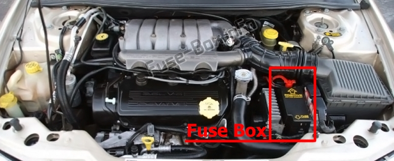
Fuse box location
Fuse Box Diagram
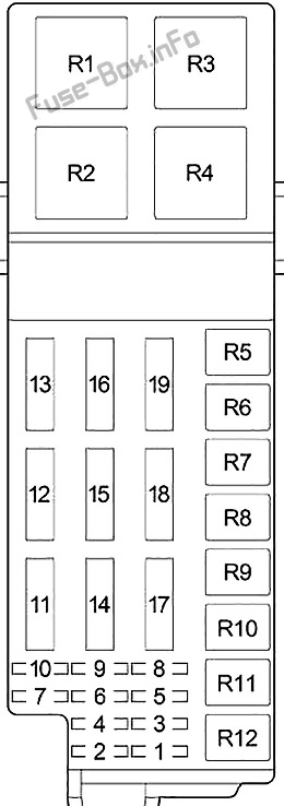
Assignment of fuses in the engine compartment
| № | Amp Rating | Description |
|---|---|---|
| 1 | 10 | O2 Sensor Downstream |
| 2 | 20 | Anti-lock braking system |
| 3 | 20 | Transmission Control Module, Transmission Control Relay |
| 4 | 20 | Stop Lamp Switch, Instrument Panel Fuses: “5” |
| 5 | 20 | Automatic Shut Down Relay (Fuel Injectors, Ignition Coil Pack (2.0L and 2.4L), Noise Suppressor (2.0L and 2.4L), Generator, Oxygen Sensor Upstream, Distributor (2.5L) EGR Solenoid, Fuse: “1”), Powertrain Control Module |
| 6 | 20 | Combination Flasher, Sentry Key Immobilizer Module |
| 7 | 10 | Ignition Switch (Instrument Panel Fuses: “11”) |
| 8 | 20 | Starter Relay, Fuel Pump Relay, Ignition Switch (Body Control Module, Clutch Interlock Switch (M/T), Transmission Control Module (EATX), Instrument Panel Fuses: “14”, “15”, “17”, Engine Compartment Fuses: “9”, “10”) |
| 9 | 10 | A/C Compressor Clutch Relay, Radiator Fan (High Speed) Relay, Radiator Fan (Low Speed) Relay, Fuel Pump Module, Instrument Cluster, Sentry Key Immobilizer Module, Brake Shift Interlock Solenoid |
| 10 | 10 | Fuel Pump Relay, Powertrain Control Module, ABS |
| 11 | 20 | Seat Belt Control Module (Convertible) |
| 12 | 40 | Rear Window Defogger Relay |
| 13 | 40 | Anti-lock braking system |
| 14 | 40 | Instrument Panel Fuses: “7”, “8” |
| 15 | 40 | Headlamp Switch, Headlamp Delay Relay (Body Control Module, Headlamp Switch, Instrument Panel Fuses: “12”, “13”), Instrument Panel Fuses: “9”, “10””18″ |
| 16 | 40 | Ignition Switch (Instrument Panel Fuses: “1”, “4”, “16”, “19”) |
| 17 | 40 | Power Top Up/Down Relays (Convertible) |
| 18 | 40 | Intermittent Wiper Relay (Wiper (High/Low) Relay) |
| 19 | 40 | A/C Compressor Clutch Relay, Radiator Fan (High Speed) Relay, Radiator Fan (Low Speed) Relay |
| Relays | ||
| R1 | Radiator Fan (High Speed) | |
| R2 | Automatic Shut Down | |
| R3 | Radiator Fan (Low Speed) | |
| R4 | Starter | |
| R5 | – | |
| R6 | A/C Compressor Clutch | |
| R7 | Power Tow (Convertible) | |
| R8 | Intermittent Wiper | |
| R9 | Wiper (High/Low) | |
| R10 | Fuel Pump | |
| R11 | Transmission Control | |
| R12 | – |


