

See other Chrysler 200:

Fuse Layout Chrysler 200 2011-2014
Contents
Cigar lighter (power outlet) fuses in the Chrysler 200 are the fuses №11 (Power Outlet Inside Center Arm Rest) and №16 (2011) or №13 (2012-2014) (Cigar Lighter) in the Engine compartment fuse box.
Table of Contents
Fuse box location
Fuse box location
The Integrated Power Module is located in the engine compartment near the air cleaner assembly.
This center contains cartridge fuses and mini fuses.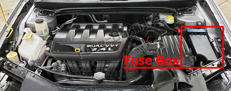
Fuse box diagrams
Fuse box diagrams
2011
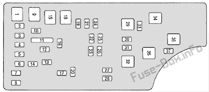
Assignment of fuses in the Integrated Power Module (2011)
| Cavity | Cartridge Fuse | Mini Fuse | Description |
|---|---|---|---|
| 1 | 40 Amp Green | — | Power Top Module -If Equipped |
| 2 | — | 20 Amp Yellow | AWD Module |
| 3 | — | 10 Amp Red | Center High Mounted Stop Light (CHMSL)/Brake Switch |
| 4 | — | 10 Amp Red | Ignition Switch |
| 5 | — | 20 Amp Yellow | Trailer Tow – If Equipped |
| 6 | — | 10 Amp Red | Power Mirror Switch/Climate Controls |
| 7 | — | 30 Amp Green | Ignition Off Draw (IOD) Sense 1 |
| 8 | — | 30 Amp Green | Ignition Off Draw (IOD) Sense 2 |
| 9 | 40 Amp Green | Battery Feed – Power Seats – If Equipped/ PZEV Air Pump – If Equipped | |
| 10 | — | 20 Amp Yellow | Instrument Panel/ Power Locks/Interior Lights |
| 11 | — | 15 Amp Lt Blue | Selectable Power Outlet (Inside Center Arm Rest) |
| 12 | — | 20 Amp Yellow | — |
| 13 | — | 20 Amp Yellow | Ignition |
| 14 | — | 10 Amp Red | Instrument Panel |
| 15 | 40 Amp Green | — | Radiator Fan Relay |
| 16 | — | 15 Amp Lt. Blue | Cigar Lighter/ Sunroof – If Equipped |
| 17 | — | 10 Amp Red | Wireless Control Module (WCM)/ Clock/Steering Control Module (SCM) |
| 18 | 40 Amp Green | — | Auto Shutdown (ASD) Relay |
| 19 | — | 20 Amp Yellow | Audio Amplifier – If Equipped |
| 20 | — | 15 Amp Lt. Blue | Radio |
| 21 | — | 10 Amp Red | Siren – If Equipped |
| 22 | — | 10 Amp Red | Ignition Run – Climate Controls/Hot Cupholder – If Equipped |
| 23 | — | 15 Amp Lt. Blue | Auto Shutdown (ASD) Relay 3 |
| 24 | — | 25 Amp Natural | Sunroof – If Equipped |
| 25 | — | 10 Amp Red | Ignition Run — Heated Mirrors – If Equipped |
| 26 | — | 15 Amp Lt. Blue | Auto Shutdown (ASD) Relay 2 |
| 27 | — | 10 Amp Red | Ignition Run – Occupant Classification Module (OCM)/ Occupant Restraint Controller (ORC) |
| 28 | — | 10 Amp Red | Ignition Run — Occupant Classification Module (OCM)/ Occupant Restraint Controller (ORC) |
| 29 | — | — | Hot Car (No Fuse Required) |
| 30 | — | 20 Amp Yellow | Ignition Run -Heated Seats – If Equipped |
| 31 | — | 10 Amp Red | Headlamp Washer -If Equipped |
| 32 | 30 Amp Pink | — | Auto Shutdown (ASD) Relay 1 |
| 33 | — | 10 Amp Red | Switch Bank/ Diagnostic Link Connector/ Powertrain Control Module (PCM) |
| 34 | 30 Amp Pink | — | Anti-Lock Brakes (ABS) Module – If Equipped/Electronic Stability Control (ESC) Module – If Equipped |
| 35 | 40 Amp Green | — | Anti-Lock Brakes (ABS) Module – If Equipped/Electronic Stability Control (ESC) Module – If Equipped |
| 36 | 30 Amp Pink | — | Passenger Door Module (PDM)/Driver Door Module (DDM) |
| 37 | — | 25 Amp Natural | Power Top Module -If Equipped |
2012, 2013 and 2014
Assignment of fuses in the Integrated Power Module (2012-2014)
| Cavity | Cartridge Fuse | Mini Fuse | Description |
|---|---|---|---|
| 1 | 40 Amp Green | — | Power Top Module -If Equipped |
| 2 | — | 20 Amp Yellow | Brake Vacuum Pump |
| 3 | 10 Amp Red | Center High Mounted Stop Light (CHMSL)/ Brake Switch | |
| 4 | — | 10 Amp Red | Ignition Switch |
| 5 | — | 20 Amp Yellow | Trailer Tow – If Equipped |
| 6 | — | 10 Amp Red | Power Mirror Switch/ Climate Controls |
| 7 | — | 30 Amp Green | Ignition Off Draw (IOD) Sense 1 |
| 8 | — | 30 Amp Green | Ignition Off Draw (IOD) Sense 2 |
| 9 | 40 Amp Green | Battery Feed – Power Seats – If Equipped | |
| 10 | 20 Amp Yellow | Instrument Panel/ Power Locks/ Interior Lights | |
| 11 | 15 Amp Lt Blue | Selectable Power Outlet (Inside Center Arm Rest) | |
| 12 | — | 20 Amp Yellow | — |
| 13 | — | 20 Amp Yellow | Ignition/Cigar Lighter |
| 14 | — | 10 Amp Red | Instrument Panel |
| 15 | 40 Amp Green | — | Radiator Fan Relay |
| 16 | — | 15 Amp Lt. Blue | Sunroof – If Equipped |
| 17 | 10 Amp Red | Wireless Control Module (WCM)/ Clock/Steering Control Module (SCM) | |
| 18 | 40 Amp Green | — | Auto Shutdown (ASD) Relay |
| 19 | — | 20 Amp Yellow | Audio Amplifier -If Equipped |
| 20 | — | 15 Amp Lt. Blue | Radio |
| 21 | — | 10 Amp Red | Siren – If Equipped |
| 22 | 10 Amp Red | Ignition Run -Climate Controls/ Hot Cupholder -If Equipped | |
| 23 | — | 15 Amp Lt. Blue | Auto Shutdown (ASD) Relay 3 |
| 24 | — | 25 Amp Natural | Sunroof – If Equipped |
| 25 | 10 Amp Red | Ignition Run — Heated Mirrors -If Equipped | |
| 26 | — | 15 Amp Lt. Blue | Auto Shutdown (ASD) Relay 2 |
| 27 | 10 Amp Red | Ignition Run -Occupant Classification Module (OCM)/ Occupant Restraint Controller (ORC) | |
| 28 | 10 Amp Red | Ignition Run — Occupant Classification Module (OCM)/ Occupant Restraint Controller (ORC) | |
| 29 | — | — | Hot Car (No Fuse Required) |
| 30 | — | 20 Amp Yellow | Ignition Run – Heated Seats – If Equipped |
| 31 | — | — | Spare |
| 32 | 30 Amp Pink | — | Auto Shutdown (ASD) Relay 1 |
| 33 | 10 Amp Red | Switch Bank/ Diagnostic Link Connector/ Powertrain Control Module (PCM) | |
| 34 | 30 Amp Pink | Anti-Lock Brakes (ABS) Module – If Equipped/Electronic Stability Control (ESC) Module – If Equipped | |
| 35 | 40 Amp Green | Anti-Lock Brakes (ABS) Module – If Equipped/Electronic Stability Control (ESC) Module – If Equipped | |
| 36 | 30 Amp Pink | Passenger Door Module (PDM)/Driver Door Module (DDM) | |
| 37 | — | 25 Amp Natural | Power Top Module -If Equipped |


