

See other Chevrolet Silverado:
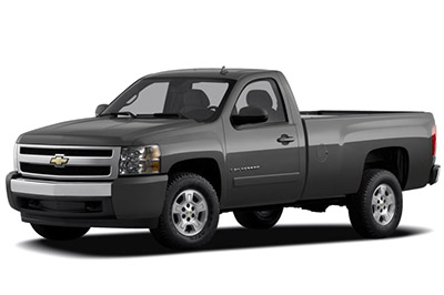
Fuse Layout Chevrolet Silverado 2007-2013
Contents
Cigar lighter / power outlet fuses in the Chevrolet Silverado are the fuses №2 (Rear Accessory Power Outlet) and №16 (Accessory Power Outlets) in the Instrument panel fuse box.
Table of Contents
Instrument Panel Fuse Box
Instrument Panel Fuse Box
Fuse box location
It is located on the driver’s side of the instrument panel, behind the cover.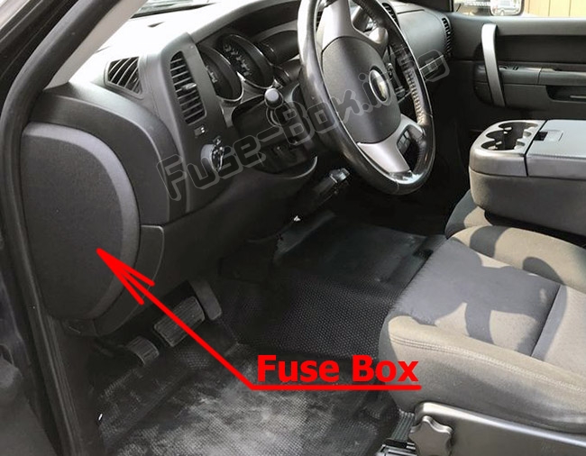
Fuse box diagram
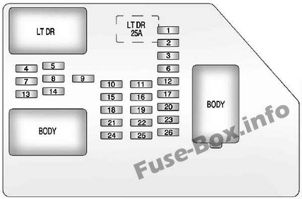
Assignment of the fuses in the Instrument Panel
| №/Name | Usage |
|---|---|
| 1 | Rear Seats |
| 2 | Rear Accessory Power Outlet |
| 3 | Steering Wheel Controls Backlight |
| 4 | Driver Door Module |
| 5 | Dome Lamps, Driver Side Turn Signal |
| 6 | Driver Side Turn Signal, Stoplamp |
| 7 | Instrument Panel Back Lighting |
| 8 | Passenger Side Turn Signal, Stoplamp |
| 9 | 2007-2008: Universal Home Remote 2009-2013: Passenger Door Module, Driver Unlock |
| 10 | Power Door Lock 2 (Unlock Feature) |
| 11 | Power Door Lock 2 (Lock Feature) |
| 12 | Stoplamps, Center High-Mounted Stoplamp |
| 13 | Rear Climate Controls |
| 14 | Power Mirror |
| 15 | Body Control Module (BCM) |
| 16 | Accessory Power Outlets |
| 17 | Interior Lamps |
| 18 | Power Door Lock 1 (Unlock Feature) |
| 19 | Rear Seat Entertainment |
| 20 | Ultrasonic Rear Parking Assist, Power Liftgate |
| 21 | Power Door Lock 1 (Lock Feature) |
| 22 | Driver Information Center (DIC) |
| 23 | Rear Wiper |
| 24 | Cooled Seats |
| 25 | Driver Seat Module, Remote Keyless Entry System |
| 26 | Driver Power Door Lock (Unlock Feature) |
| Circuit Breaker | |
| LT DR | Driver Side Power Window Circuit Breaker |
| Harness Connector | |
| LT DR | Driver Door Harness Connection |
| BODY | Harness Connector |
| BODY | Harness Connector |
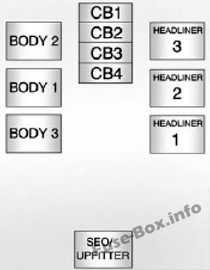
Center instrument panel fuse box
Center instrument panel fuse box
It is located underneath the instrument panel, to the left of the steering column.
| Harness Connector | Usage |
|---|---|
| BODY 2 | Body Harness Connector 2 |
| BODY 1 | Body Harness Connector 1 |
| BODY 3 | Body Harness Connector 3 |
| HEADLINER 3 | Headliner Harness Connector 3 |
| HEADLINER 2 | Headliner Harness Connector 2 |
| HEADLINER 1 | Headliner Harness Connector 1 |
| SEO/ UPFITTER | Special Equipment Option Upfitter Harness Connector |
| Circuit Breaker | |
| CB1 | Passenger Side Power Window Circuit Breaker |
| CB2 | Passenger Seat Circuit Breaker |
| CB3 | Driver Seat Circuit Breaker |
| CB4 | Rear Sliding Window |
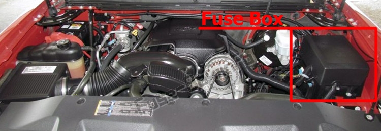
Engine Compartment Fuse Box
Engine Compartment Fuse Box
Fuse box location
Fuse box diagram
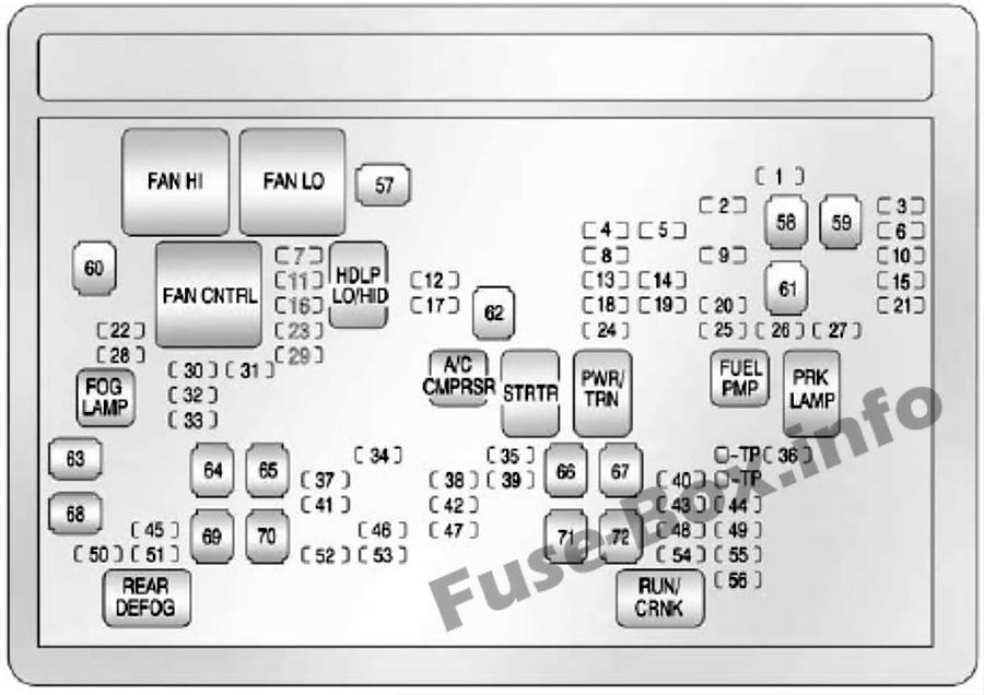
Assignment of the fuses and relay in the Engine Compartment
| №/Name | Usage |
|---|---|
| 1 | Right Trailer Stop/ Turn Lamp |
| 2 | Electronic Suspension Control, Automatic Level Control Exhaust |
| 3 | Left Trailer Stop/ Turn Lamp |
| 4 | Engine Controls |
| 5 | Engine Control Module, Throttle Control |
| 6 | Trailer Brake Controller |
| 7 | Front Washer |
| 8 | Oxygen Sensor |
| 9 | Antilock Brakes System 2 |
| 10 | Trailer Back-up Lamps |
| 11 | Driver Side Low-Beam Headlamp |
| 12 | Engine Control Module (Battery) |
| 13 | Fuel Injectors, Ignition Coils (Right Side) |
| 14 | Transmission Control Module (Battery) |
| 15 | Vehicle Back-up Lamps |
| 16 | Passenger Side Low-Beam Headlamp |
| 17 | Air Conditioning Compressor |
| 18 | Oxygen Sensors |
| 19 | Transmission Controls (Ignition) |
| 20 | Fuel Pump |
| 21 | Fuel System Control Module |
| 22 | Not Used |
| 23 | Not Used |
| 24 | Fuel Injectors, Ignition Coils (Left Side) |
| 25 | Trailer Park Lamps |
| 26 | Driver Side Park Lamps |
| 27 | Passenger Side Park Lamps |
| 28 | Fog Lamps |
| 29 | Horn |
| 30 | Passenger Side High-Beam Headlamp |
| 31 | Daytime Running Lamps (DRL) |
| 32 | Driver Side High-Beam Headlamp |
| 33 | Daytime Running Lamps 2 |
| 34 | Sunroof |
| 35 | Key Ignition System, Theft Deterrent System |
| 36 | Windshield Wiper |
| 37 | SEO B2 Upfitter Usage (Battery) |
| 38 | Electric Adjustable Pedals |
| 39 | Climate Controls (Battery) |
| 40 | Airbag System (Ignition) |
| 41 | Amplifier |
| 42 | Audio System |
| 43 | Miscellaneous (Ignition), Cruise Control |
| 44 | Not Used |
| 45 | Airbag System (Battery) |
| 46 | Instrument Panel Cluster |
| 47 | Power Take-Off |
| 48 | Auxiliary Climate Control (Ignition) Compass-Temperature Mirror |
| 49 | Center High-Mounted Stoplamp (CHMSL) |
| 50 | Rear Defogger |
| 51 | Heated Mirrors |
| 52 | SE0B1 Upfitter Usage (Battery) |
| 53 | Cigarette Lighter, Accessory Power Outlet |
| 54 | Automatic Level Control CompressorRelay SEO Upfitter Usage |
| 55 | Climate Controls (Ignition) |
| 56 | Engine Control Module, Secondary Fuel Pump (Ignition) |
| J-Case Fuses | |
| 57 | Cooling Fan 1 |
| 58 | Not Used |
| 59 | Heavy Duty Antilock Brake System |
| 60 | Cooling Fan 2 |
| 61 | Antilock Brake System 1 |
| 62 | Starter |
| 63 | Stud 2 (Trailer Brakes) |
| 64 | Left Bussed Electrical Center 1 |
| 65 | Not Used |
| 66 | Heated Windshield Washer System / Not Used |
| 67 | Four-Wheel Drive System / Transfer Case |
| 68 | Stud 1 (Trailer Connector Battery Power) (Optional -40A Fuse Required) |
| 69 | Mid-Bussed Electrical Center 1 |
| 70 | Climate Control Blower |
| 71 | Not Used |
| 72 | Left Bussed Electrical Center 2 |
| Relays | |
| FAN HI | Cooling Fan High Speed |
| FAN LO | Cooling Fan Low Speed |
| FAN CNTRL | Cooling Fan Control |
| HDLP LO/HID | Low-Beam Headlamp |
| FOG LAMP | Front Fog Lamps |
| A/C CMPRSR | Air Conditioning Compressor |
| STRTR | Starter |
| PWR/TRN | Powertrain |
| FUEL PMP | Fuel Pump |
| PRK LAMP | Parking Lamps |
| REAR DEFOG | Rear Defogger |
| RUN/CRNK | Switched Power |
Hybrid Auxiliary Engine Compartment Fuse Block
Hybrid Auxiliary Engine Compartment Fuse Block
The fuse block is located in the engine compartment near the front of the vehicle.
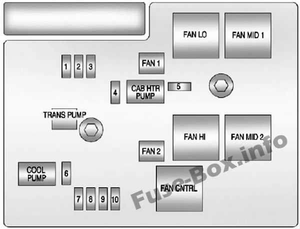
Hybrid Auxiliary Engine Compartment Fuse Block
| №/Name | Usage |
|---|---|
| 1 | ACPO (SUV Only) |
| 2 | BECM FAN |
| 3 | ACCM |
| 4 | CAB HTR PMP |
| 5 | EMPTY |
| 6 | COOL PUMP |
| 7 | EPS |
| 8 | Drive Motor/Generator Control Module 1 |
| 9 | Drive Motor/Generator Control Module 2 |
| 10 | BECM |
| J-Case fuses | |
| FAN 1 | Cooling Fan 1 |
| TRANS PUMP | Auxiliary Transmission Fluid Pump |
| FAN 2 | Cooling Fan 2 |
| CAB HTR PMP | Cab Heater Pump |
| Relays | |
| CAB HTR PUMP | Cabin Heater Pump |
| COOL PUMP | Coolant Pump |
| FAN LOW | Cooling Fan Low Speed Relay |
| FAN MID 1 | Cooling Fan Mid 1 |
| FAN HI | Cooling Fan High Speed Relay |
| FAN MID 2 | Cooling Fan Mid 2 |
| FAN CNTRL | Cooling Fan Control |


