Fuse Layout Buick LaCrosse 2005-2009
Contents
Table of Contents
Passenger compartment fuse box
Passenger compartment fuse box
Fuse Box Location
It is located on the right side of the instrument panel, behind the cover.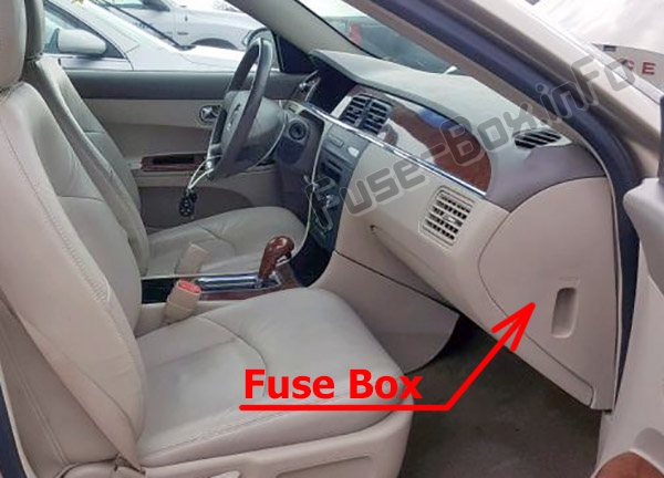
Fuse box diagram
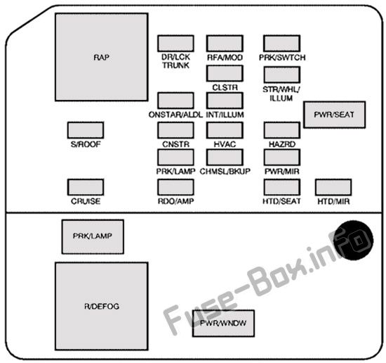
Assignment of the fuses and relays in the Passenger compartment
| Name | Description |
|---|---|
| DR/LCK TRUNK | Door Locks, Trunk |
| RFA/MOD | Remote Keyless Entry |
| PRK/SWTCH | Ignition Key Lock |
| CLSTR | Cluster |
| STR/WHL/ ILLUM | Steering Wheel Controls Illumination |
| ONSTAR/ALDL | OnStar®, Data Link |
| INT/ILLUM | Interior Lamps |
| PWR/SEAT | Power Seat |
| S/ROOF | Sunroof |
| CNSTR | Canister Vent |
| HVAC | Climate Control System |
| HAZRD | Turn Signal, Hazard |
| PRK/LAMP | Park Lamps |
| CHMSL/BKUP | Center-High-Mounted Stoplamp/Back-up Lamps |
| PWR/MIR | Power Mirrors |
| CRUISE | Cruise Control |
| RDO/AMP | Radio, Amplifier |
| HTD/SEAT | Heated Seats |
| HTD/MIR | Heated Mirrors |
| PWR/WNDW | Power Window |
| Relays | |
| RAP | Retained Accessory Power |
| PRK/LAMP | Park Lamp Relay |
| R/DEFOG | Rear Defogger Relay |
Fuse Box in the engine compartment
Fuse Box in the engine compartment
Fuse Box Location
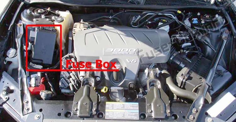
Fuse box diagram (3.6L and 3.8L V6 engines)
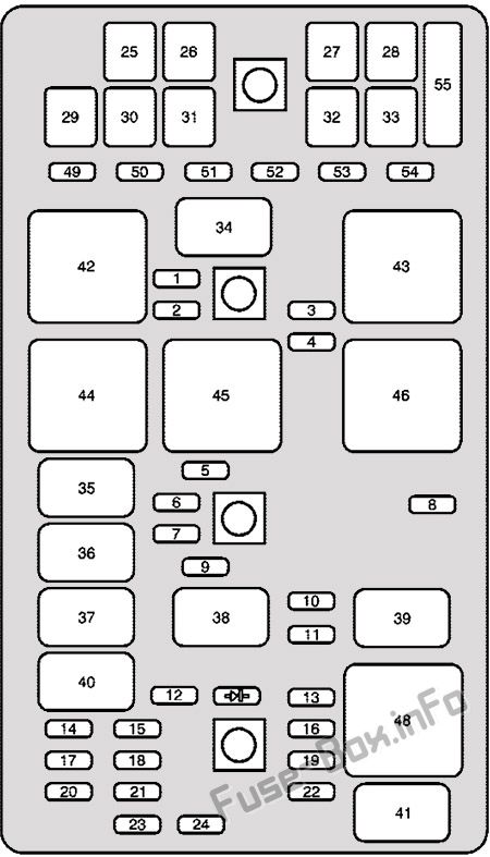
Assignment of the fuses and relays in the engine compartment (3.6L & 3.8L V6 engines)
| № | Description |
|---|---|
| Mini Fuses | |
| 1 | Driver Side High-Beam |
| 2 | Passenger Side High-Beam |
| 3 | Driver Side Low-Beam |
| 4 | Passenger Side Low-Beam |
| 5 | Windshield Wiper |
| 6 | Washer/Regulated Voltage Control |
| 7 | Fog Lamps |
| 8 | Transmission Control Module |
| 9 | Supplemental Inflatable Restraint |
| 10 | Auxiliary Power |
| 11 | Horn |
| 12 | Emission |
| 13 | Air Conditioner Clutch |
| 14 | Oxygen Sensor |
| 15 | Powertrain Control Module |
| 16 | Powertrain Control Module, Electronic Throttle Control |
| 17 | Electronic Throttle Control |
| 18 | Display |
| 19 | Antilock Brake Solenoid |
| 20 | Fuel Injector |
| 21 | Transmission Solenoid |
| 22 | Fuel Pump |
| 23 | Antilock Brake System |
| 24 | Ignition |
| J-Style fuse | |
| 25 | Air Pump |
| 26 | Battery Main 1 |
| 27 | Battery Main 2 |
| 28 | Battery Main 3 |
| 29 | Fan 1 |
| 30 | Battery Main 4 |
| 31 | Antilock Brake System Motor |
| 32 | Fan 2 |
| 33 | Starter |
| Micro-Relays | |
| 34 | Headlamp High-Beam |
| 35 | Headlamp Driver Module |
| 36 | Fog Lamp |
| 37 | Ignition 1 |
| 38 | Air Conditioning Compressor |
| 39 | Horn |
| 40 | Powertrain |
| 41 | Fuel Pump |
| Mini-Relays | |
| 42 | Fan 1 |
| 43 | Fan 3 |
| 44 | Windshield Wiper High |
| 45 | Windshield Wiper |
| 46 | Fan 2 |
| 48 | Crank |
| 49-54 | Spare fuses |
| 55 | Fuse Puller |
| diode | Air Conditioner Compressor Clutch Diode |
Fuse box diagram (5.3L V8 Engine)
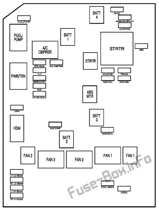
Assignment of the fuses and relays in the engine compartment (5.3L V8 Engine)
| Name | Description |
|---|---|
| HVAC | Climate Control System |
| FUEL/PUMP | Fuel Pump |
| AIRBAG/ DISPLAY | Airbag, Display |
| COMPASS | Compass |
| ABS | Antilock Brake System |
| ETC/ECM | Electronic Throttle Control, Engine Control Module |
| A/C CMPRSR | Air Conditioning Compressor |
| INJ 1 | Injectors 1 |
| ECM/TCM | Engine Control Module, Transmission Control Module |
| TRANS | Transmission |
| EMISSIONS1 | Emissions 1 |
| ABS SOL | Antilock Brake Solenoid |
| ECM IGN | Engine Control Module, Ignition |
| INJ 2 | Injectors 2 |
| EMISSIONS2 | Emissions 2 |
| WPR | Windshield Wipers |
| AUX PWR | Auxiliary Power |
| WSW/RVC | Windshield Washer, Regulated Voltage Control |
| LT LO BEAM | Driver Side Low-Beam Headlamp |
| RT LO BEAM | Passenger Side Low-Beam Headlamp |
| FOG LAMPS | Fog Lamps |
| LT HI BEAM | Driver Side High-Beam Headlamp |
| HORN | Horn |
| RT HI BEAM | Passenger Side High-Beam Headlamp |
| BATT 4 | Battery 4 |
| BATT 1 | Battery 1 |
| STRTR | Starter |
| ABS MTR | Antilock Brake System Motor |
| BATT 3 | Battery 3 |
| BATT 2 | Battery 2 |
| FAN 2 | Cooling Fan 2 |
| FAN 1 | Cooling Fan 1 |
| Relays | |
| FUEL/PUMP | Fuel Pump |
| A/C CMPRSR | Air Conditioning Compressor |
| PWR/TRN | Powertrain |
| STRTR | Starter |
| FAN 1 | Cooling Fan 1 |
| FAN 2 | Cooling Fan 2 |
| FAN 3 | Cooling Fan 3 |
| HDM | Headlamp Driver Module |


