Fuse Layout Suzuki Swift 2004-2010
Contents
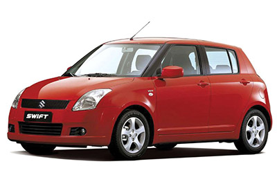
Cigar lighter (power outlet) fuses in the Suzuki Swift are the fuses #5 (Cigar) and #6 (Accessory) in the Instrument panel fuse box.
Table of Contents
Passenger Compartment Fuse Box
Passenger Compartment Fuse Box
Fuse box location
The fuse box is located under the instrument panel (on the driver’s side).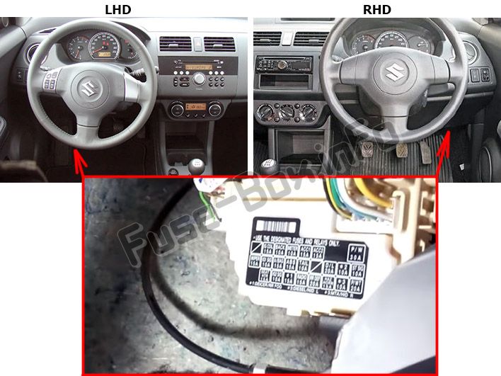
Fuse box diagram
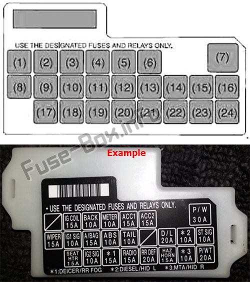
Assignment of the fuses in the instrument panel
| № | Amp | Function/component |
|---|---|---|
| 1 | – | Not used |
| 2 | 15 | Ignition coil |
| 3 | 10 | Back-up light |
| 4 | 10 | Meter |
| 5 | 15 | Cigar |
| 6 | 15 | Accessory |
| 7 | 30 | Power window |
| 8 | 15 | Wiper / Washer |
| 9 | 10 | Power steering / IG1 Signal |
| 10 | 15 | Air bag |
| 11 | 10 | Anti-lock brake system |
| 12 | 10 | Tail light |
| 13 | – | Not used |
| 14 | 20 | Door lock |
| 15 | 10 | Immobilizer (Diesel Engine) |
| 16 | 10 | Starting motor |
| 17 | – | Not used |
| 18 | 10 | Heater / IG2 Signal |
| 19 | 15 | RR fog lamp |
| 20 | 15 | Radio / Dome |
| 21 | 20 | Rear defogger |
| 22 | 15 | Horn / Hazard |
| 23 | – | Not used |
| 24 | – | Not used |
Fuse Box in the Engine Compartment
Fuse Box in the Engine Compartment
Fuse box location
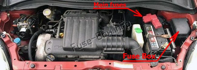
Fuse box diagram (Gasoline)
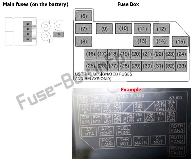
Assignment of the fuses and relays in the engine compartment (Gasoline)
| № | Amp | Function/component |
|---|---|---|
| 1 | 80 | All electric load |
| 2 | 50 | Power window, Ignition, Wiper, Starter |
| 3 | 50 | Tail light, Rear defogger, Door lock, Hazard/Horn, Dome |
| 4 | 80 | Heater, Air compressor, Power steering |
| 5 | 80 | Radiator fan, Front fog light, Head light |
| 16 | 30 | Heater |
| 17 | 15 | FI |
| 18 | 10 | Air compressor |
| 19 | – | Not used |
| 20 | 15 | Brake light switch |
| 21 | 30 | ABS control module |
| 22 | 30 | Starting motor |
| 23 | – | Not used |
| 24 | 50 | Power steering control module |
| 25 | 30 | Ignition switch |
| 26 | 30 | Radiator fan |
| 27 | – | Not used |
| 28 | 30 | ABS control module |
| 29 | – | Not used |
| 30 | – | Not used |
| 31 | 15 | Front fog light |
| 32 | 15 | Headlight (Left) |
| 33 | 15 | Headlight (Right) |
| Relays | ||
| 6 | Radiator fan relay #1 | |
| 7 | Radiator fan relay #2 | |
| 8 | Radiator fan relay #3 | |
| 9 | Starting motor relay | |
| 10 | Main relay | |
| 11 | Not used | |
| 12 | Front fog light relay | |
| 13 | Fuel pump relay | |
| 14 | Air compressor relay | |
| 15 | Not used |
Fuse box diagram (Diesel)
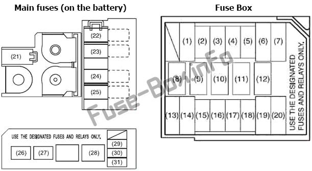
Assignment of the fuses and relays in the engine compartment (Diesel)
| № | Amp | Function/component |
|---|---|---|
| 1 | 30 | Starting motor |
| 2 | 10 | Air compressor |
| 3 | 15 | Fuel pump |
| 4 | 30 | FI |
| 5 | 30 | Heater |
| 6 | 30 | Radiator fan |
| 7 | 50 | Power steering control module |
| 13 | 30 | ABS control module |
| 14 | 30 | ABS control module |
| 15 | 15 | Brake light switch |
| 16 | 15 | Headlight (Right) |
| 17 | 15 | Headlight (Left) |
| 18 | 15 | Front fog light |
| 19 | 30 | Ignition switch |
| 20 | 50 | Power window, Ignition, Wiper, Starter |
| 21 | 100 | Main |
| 22 | 100 | EPS, A/C, Fuel pump, IG1 |
| 23 | 100 | Lamps, ABS, ACC, IG2 |
| 24 | 50 | Junction box |
| 25 | 80 | Glow controller |
| 29 | 20 | F.l. |
| 30 | 20 | ECU (if equipped) |
| 31 | 10 | ECU, EGR |
| Relays | ||
| 8 | Radiator fan relay #1 | |
| 9 | Radiator fan relay #2 | |
| 10 | Radiator fan relay #3 | |
| 11 | Air compressor relay | |
| 12 | Starting motor relay | |
| 26 | Fog Lamp relay | |
| 27 | Fuel pump relay | |
| 28 | F.l. main relay |


