

Fuse Layout Lincoln Nautilus 2019-…
Contents

Cigar lighter (power outlet) fuses in the Lincoln Nautilus are the fuses #5 (Power point 3 – back of console), #10 (Power point 5-main bin), #16 (Power point 2 – console bin) and #17 (Power point 4 – luggage compartment) in the Engine compartment fuse box.
Table of Contents
Fuse box location
Passenger compartment
The fuse panel is located under the instrument panel to the left of the steering column (It may be easier to access the fuse panel if you remove the finish trim piece).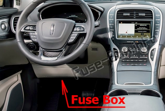
Engine compartment
The power distribution box is located in the engine compartment (left-side).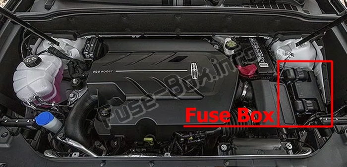
Power Distribution Box – Bottom
There are fuses located on the bottom of the fusebox.
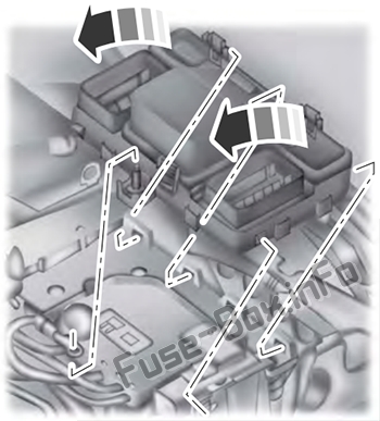
To access, do the following:
1) Release the two latches, located on both sides of the fusebox.
2) Raise the inboard side of the fusebox from the cradle.
3) Move the fusebox toward the center of the engine compartment.
4) Pivot the outboard side of the fusebox to access the bottom side.
Fuse box diagrams
2019
Passenger compartment
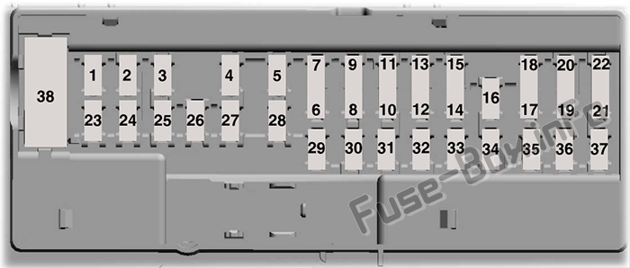
Assignment of the fuses in the passenger compartment (2019)
| № | Amper Rating | Protected Components |
|---|---|---|
| 1 | – | Not used. |
| 2 | 7.5 A | Memory seats. Lumbar. Driver seat module logic power. Wireless accessory charging. |
| 3 | 20A | Driver door unlock. |
| 4 | 5A | Not used (spare). |
| 5 | 20A | Subwoofer amplifier. |
| 6 | 10A | USB charger. |
| 7 | 10A | Not used (spare). |
| 8 | 10A | Security horn relay. |
| 9 | 10A | Rear seat entertainment system module. |
| 10 | 5A | Keypad. Power liftgate module logic power. Hands free liftgate module. SYNC 3 module. Embedded Modem. |
| 11 | 5A | Combined sensing module. |
| 12 | 7.5 A | Climate control module. Gear shift module. |
| 13 | 7.5 A | Cluster. Steering column control module. Smart datalink connector (gateway) module. |
| 14 | 10A | Extended power module – power. |
| 15 | 10A | Datalink power. |
| 16 | 15A | Not used (spare). |
| 17 | 5A | Not used (spare). |
| 18 | 5A | Not used (spare). |
| 19 | 7.5 A | Extended power module – Run/Start. |
| 20 | 7.5 A | Not used (spare). |
| 21 | 5A | Humidity sensor. |
| 22 | 5A | Occupant classification sensor. |
| 23 | 10A | Delayed accessory (power inverter logic, moonroof logic, driver window switch power). |
| 24 | 20A | Central lock unlock. |
| 25 | 30A | Driver door (window, mirror). Driver door module. Driver door lock indicator. Driver lock switch illumination. |
| 26 | 30A | Front passenger door (window, mirror). Front passenger door module. Front passenger lock indicator. Front passenger switch illumination (window, lock). |
| 27 | 30A | Moonroof. |
| 28 | 20A | Amplifier. |
| 29 | 30A | Rear driver side door smart window. |
| 30 | 30A | Rear passenger side door smart window. |
| 31 | 15A | Not used (spare). |
| 32 | 10A | Voice control (SYNC). Radio transceiver module. |
| 33 | 20A | Radio. |
| 34 | 30A | Run-start bus (fuse 19, 20, 21, 22, 35, 36, 37, circuit breaker 38). |
| 35 | 5A | Not used (spare). |
| 36 | 15A | Auto-dimming rear view mirror. Rear heated seat module logic power. Suspension module. |
| 37 | 20A | Not used (spare). |
| 38 | – | Not used. |
Engine compartment
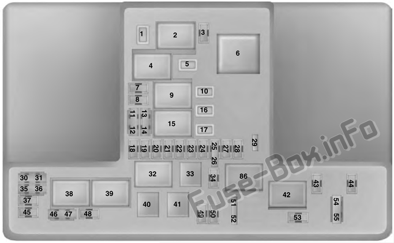
Assignment of the fuses and relays in the engine compartment (2019)
| № | Amper Rating | Protected Components |
|---|---|---|
| 1 | 30A | Second row power seat. |
| 2 | — | Starter relay. |
| 3 | 15A | Rear wiper. Rain sensor Rear wash relay coil. |
| 4 | — | Blower motor relay. |
| 5 | 20A | Power point 3 – back of console. |
| 6 | — | Not used. |
| 7 | 20A | Powertrain control module – vehicle power 1. |
| 8 | 20A | Powertrain control module – vehicle power 2. |
| 9 | — | Powertrain control module relay. |
| 10 | 20A | Power point 5-main bin. |
| 11 | 15A | Powertrain control module – vehicle power 4. |
| 12 | 15A | Powertrain control module – vehicle power 3. |
| 13 | — | Not used. |
| 14 | — | Not used. |
| 15 | — | Run-start relay. |
| 16 | 20A | Power point 2 – console bin. |
| 17 | 20A | Power point 4 – luggage compartment. |
| 18 | 20A | Right High Intensity Discharge headlamp. |
| 19 | 10A | Run-start electronic power assist steering. |
| 20 | 10A | Run/start lighting. |
| 21 | 15A | Run-start relay. |
| 22 | 10A | Air conditioner clutch solenoid. |
| 23 | 15A | Front split view camera. Rear view camera. Front split view camera module. Blind spot information system. Adaptive cruise control. |
| 24 | 10A | Not used (spare). |
| 25 | 10A | Run-start anti-lock brake system. |
| 26 | 10A | Run-start powertrain control module. |
| 27 | 5A | Not used (spare). |
| 28 | 10A | Rear washer pump. |
| 29 | 5A | Not used (spare). |
| 30 | — | Not used. |
| 31 | — | Not used. |
| 32 | — | Electronic fan 1 relay. |
| 33 | — | A/C clutch relay. |
| 34 | 15A | Glove box release. |
| 35 | — | Not used. |
| 36 | — | Not used. |
| 37 | 10A | Power transfer unit fan. Transfer case cooling fan relay. |
| 38 | — | Electronic fan 2 relay. |
| 39 | — | Electric fan 3 relay. |
| 40 | — | Horn relay. |
| 41 | — | Left high beam and stop lamp relay. |
| 42 | — | Fuel pump relay. |
| 43 | 15A | Second row easy fold seat release. |
| 44 | 20A | Left High Intensity Discharge headlamp. |
| 45 | — | Not used. |
| 46 | — | Not used. |
| 47 | — | Not used. |
| 48 | 15A | Left high beam and stop lamp. |
| 49 | — | Not used. |
| 50 | 20A | Horn. |
| 51 | — | Not used. |
| 52 | — | Not used. |
| 53 | 10A | Massaging seats. |
| 54 | 10A | Brake on off switch. |
| 55 | 10A | Alternator A-line. |
| 86 | — | Not used. |
Engine compartment (bottom)
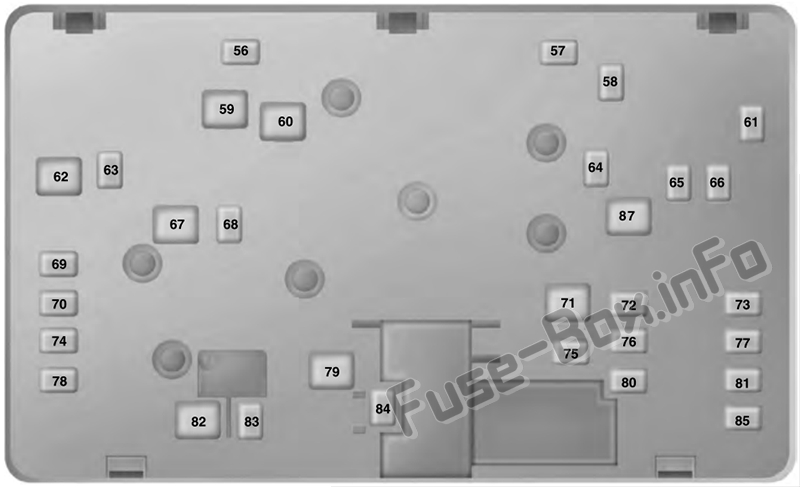
Assignment of the fuses in the Power Distribution Box – Bottom (2019)
| № | Amper Rating | Protected Components |
|---|---|---|
| 56 | — | Not used. |
| 57 | 20A | Not used (spare). |
| 58 | 30A | Fuel pump feed. |
| 59 | 40A | Electronic fan 3. |
| 60 | 40A | Electronic fan 1. |
| 61 | — | Not used. |
| 62 | 50A | Body control module 1. |
| 63 | 25A | Electronic fan 2. |
| 64 | 15A | Headlamp washer. |
| 65 | 20A | Front heated seat. |
| 66 | 15A | Heated wiper park. |
| 67 | 50A | Body control module 2. |
| 68 | 40A | Heated rear window. |
| 69 | 30A | Anti-lock brake system valves. |
| 70 | 30A | Passenger seat. |
| 71 | – | Not used. |
| 72 | 20A | Transmission oil pump. |
| 73 | 20A | Rear heated seats. |
| 74 | 30A | Driver seat module. |
| 75 | 25A | Wiper motor 1. |
| 76 | 30A | Power liftgate module. |
| 77 | 30A | Climate control seat module. |
| 78 | 40A | Trailer tow. |
| 79 | 40A | Blower motor. |
| 80 | 25A | Wiper motor 2. |
| 81 | 40A | 110 volt inverter. |
| 82 | – | Not used. |
| 83 | 20A | TRCM. |
| 84 | 30A | Starter solenoid. |
| 85 | 30A | Not used (spare). |
| 87 | 60A | Anti-lock brake system pump. |


