See other Range Rover:
Fuse Layout Range Rover 1994-2002
Contents
Table of Contents
Passenger Compartment Fuse Box
Passenger Compartment Fuse Box
Fuse Box Location
The fuse box is located behind the lid under the front right seat.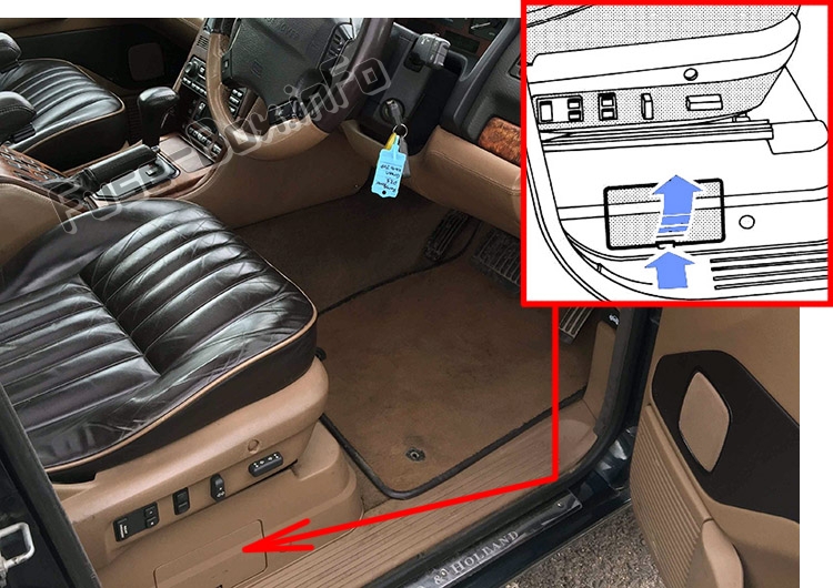
Fuse Box Diagram
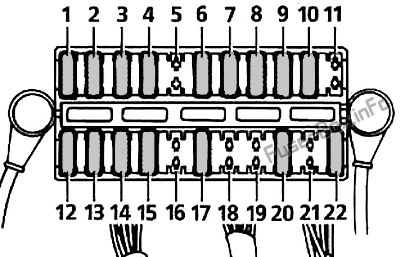
Assignment of the fuses under the seat
| № | Amp | Description |
|---|---|---|
| 1 | 10A | Instrument pack, Clock, Radio, Centre console switch pack |
| 2 | 30A | Right-hand rear window, Seat heaters |
| 3 | 5A | EAT ECU – Battery supply |
| 4 | 30A | Transfer box ECU – Battery supply |
| 5 | – | Spare |
| 6 | 10A | Rear view mirror dip, Spare 1 ignition, Sun visor illumination;
Up to 1999: EAT ECU Ignition supply, Transfer box ECU ignition supply |
| 7 | 10A | Up to 1999: Airbag;
After 1999: EAT ECU Ignition supply, Transfer box ECU ignition supply. |
| 8 | 30A | Car phone, radio, front cigar lighter, HEVAC;
Up to 1999: Aerial amplifier |
| 9 | 20A | Left/Right front ICE amplifier, Left/Right door Battery 2 |
| 10 | 30A | Right-hand seat Battery 1, Right-hand seat battery 2, Right-hand seat lumbar, Rear cushion battery 1, Fore/aft adjustment battery 1, Front cushion battery 2, backrest battery 2, headrest battery 2 |
| 11 | – | Spare (When spare fuse of at least 5 Amps is inserted, transfer box moves to neutral position) |
| 12 | 30A | Heated rear window, Left-hand rear window |
| 13 | 20A | Shift interlock solenoid, Sunroof;
Up to 1999: Key inhibit solenoid |
| 14 | 30A | Left/Right rear central door locking, Fuel flap release, trailer battery supply |
| 15 | 20A | Left/Right rear ICE amplifiers, Courtesy/Load space lamps, ICE subwoofer Right-hand rear courtesy lamp, RF remote receiver, Tail door central door locking, Rear wiper |
| 16 | 30A | Spare |
| 17 | 10A | Brake switch feed;
Up to 1999: HEVAC ignition signal, Air suspension switches |
| 18 | 30A | 6th outstation battery supply (not fitted) |
| 19 | – | Spare |
| 20 | 30A | Left-hand seat battery 1, Left-hand seat battery 2, Left-hand seat lumbar, Rear cushion battery 1, Fore/aft adjustment battery 1, Backrest battery 2, Front cushion battery 2, Headrest battery 2 |
| 21 | – | Spare |
| 22 | 30A | Left-hand door battery 1 (front window only), Right-hand door battery 2 (front window only) |
Engine Compartment Fuse Box
Engine Compartment Fuse Box
Fuse Box Location
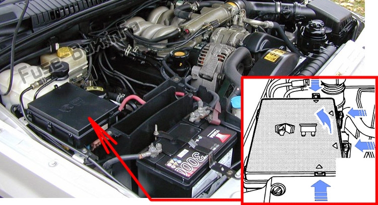
Fuse Box Diagram
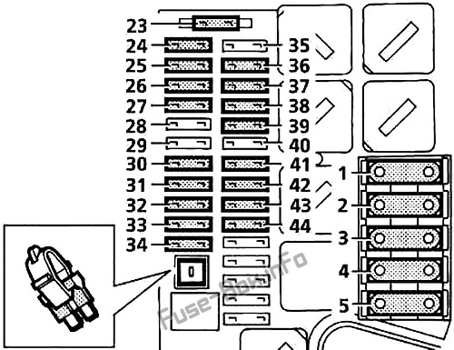
Assignment of the fuses in the engine compartment
| № | Amp | Description |
|---|---|---|
| 1 | 60A | |
| 2 | 50A | Spare |
| 3 | 40A | ABS pump |
| 4 | 60A | |
| 5 | 60A | |
| 23 | 10A | Airbag SRS |
| 24 | 5A | ABS |
| 25 | 20A | Front wiper system, headlight washers |
| 26 | 20A | Engine management system (EMS) |
| 27 | 10A | Air conditioning compressor |
| 28 | 15A/30A | Gasoline: Ignition coils (30A); Diesel: Cooling fan (15A) |
| 29 | 10A | Air suspension |
| 30 | 30A | Heated front screen |
| 31 | 30A | Air-conditioning |
| 32 | 30A | Heated front screen |
| 33 | 5A | Diagnostics, battery back-up sounder |
| 34 | 30A | Heater blower |
| 35 | 10A | Air conditioning, air suspension |
| 36 | 30A | Air-conditioning |
| 37 | 30A | Engine management system (EMS) |
| 38 | 30A | ABS |
| 39 | 20A | Fuel pump |
| 40 | 40A | Starter motor, air suspension |
| 41 | 20A | Horn |
| 42 | 10A | Heating & ventilation, key inhibit |
| 43 | 30A | Heater blower |
| 44 | 30A | Engine management system (EMS) |


