

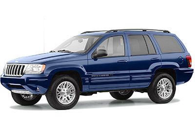
See other Jeep Grand Cherokee:


Fuse Layout Jeep Grand Cherokee 1999-2005
Contents
Cigar lighter (power outlet) fuses in the Jeep Grand Cherokee are the fuses #9 and #26 in the Instrument panel fuse box.
Table of Contents
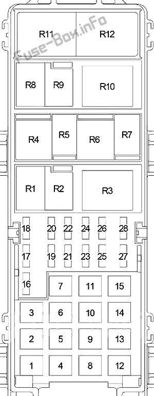
Passenger Compartment Fuse Box
Fuse box location
It is located under the instrument panel on the driver’s side, behind a plastic cover near the OBD2 port.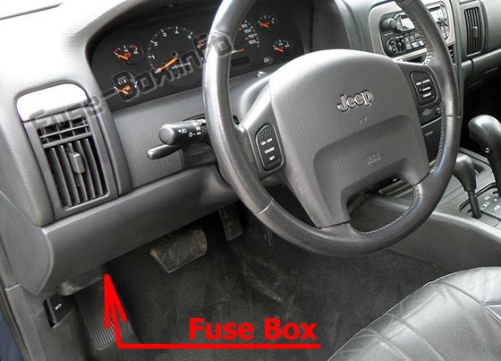
Fuse box diagram
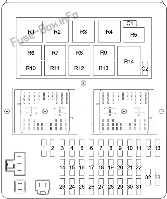
Assignment of the fuses and relay in the instrument panel
| № | Amp rating | Description |
|---|---|---|
| 1 | – | Spare |
| 2 | – | Spare |
| 3 | 10 | Left Headlamp (High Beam) |
| 4 | 15 | Combination Flasher |
| 5 | 25 | Radio, Amplifier |
| 6 | 15 | Park Lamp Relay (Park Lamp, Tail Lamp, License Lamp, Trailer Tow Connector, Headlamp Leveling Switch) |
| 7 | 10 | Body Control Module, Underhood Lamp, Sentry Key Immobilizer Module, Automatic Zone Control Module, Automatic Headlamp Light Sensor/VTSS LED, Remote Keyless Module |
| 8 | 15 | Rear Wiper Motor, Courtesy Lamp, Glove Box Lamp, Cargo Lamp, Overhead Map Lamp, Door Handle Lamp, Vehicle Information Center, Liftgate Flip-Up Push Button Switch, Security System Module, Visor/Vanity Lamp |
| 9 | 20 | Front Power Outlet, Rear Power Outlet, Power Connector |
| 10 | 20 | Adjustable Pedals |
| 11 | 10 | Automatic Zone Control Module (AZC), Manual Temperature Control (MTC) |
| 12 | 10 | Fuel Pump Relay, Automatic Shut Down Relay, Powertrain Control Module, Transmission Control Relay (4.7L) |
| 13 | – | Spare |
| 14 | 10 | Left Headlamp (Low Beam) |
| 15 | 10 | Right Headlamp (Low Beam) |
| 16 | 10 | Right Headlamp (High Beam) |
| 17 | 10 | Data Link Connector, Instrument Cluster |
| 18 | 20 or 30 | Trailer Tow Brake Lamp Relay, Electric Brake |
| 19 | 10 | ABS |
| 20 | 10 | Combination Flasher, Automatic Zone Control Module (AZC), Manual Temperature Control (MTC), Temperature Valve Actuator (MTC), Transmission Solenoid/TRS Assembly (4.7L), Park/Neutral Position Switch (4.0L, 3.1L TD), Driver/Passenger Heated Seat Switch |
| 21 | 10 | Gasoline: Air Conditioner Compressor Clutch Relay, EVAP/Purge Solenoid, Brake Transmission Shift Interlock Solenoid;
Diesel: Fuel Heater Relay, Engine Control Module, Brake Transmission Shift Interlock Solenoid |
| 22 | 10 | Body Control Module, Instrumeent Cluster, Sentry Key Immobilizer Module, Vehicle Information Center, Automatic Day/Night Mirror, Security System Module |
| 23 | 15 | Stop Lamp Switch |
| 24 | 15 | Front Fog Lamp Relay, Body Control Module |
| 25 | 20 | Sunroof Delay Relay, Body Control Module |
| 26 | 15 | Cigar Lighter |
| 27 | 15 | Rear Fog Lamp Relay |
| 28 | 10 | Body Control Module |
| 29 | 10 | Cigar Lighter Relay, Right Multi-Function Switch |
| 30 | 15 | Radio |
| 31 | 10 | Starter Relay, Transmission Control Module (4.7L) |
| 32 | 10 | Airbag Control Module |
| 33 | 10 | Airbag Control Module |
| C1 | 20 | Front Wiper Motor, Wiper (On/Off) Relay, Wiper (High/Low) Relay (Circuit Breaker) |
| C2 | 20 | Power Seats (Circuit Breaker) |
| C3 | – | Spare |
| Relay | ||
| R1 | Low Beam / Daytime Running Lamp | |
| R2 | Cigar Lighter | |
| R3 | Combination Flasher | |
| R4 | Rear Window Defogger | |
| R5 | Rear Fog Lamp | |
| R6 | Low Beam | |
| R7 | High Beam | |
| R8 | Sunroof Delay | |
| R9 | – | |
| R10 | Front Fog Lamp | |
| R11 | – | |
| R12 | Park Lamp | |
| R13 | – | |
| R14 | – |
Engine Compartment Fuse Box
Fuse box location
The Power Distribution Center is located near the battery (left or right depending on the version).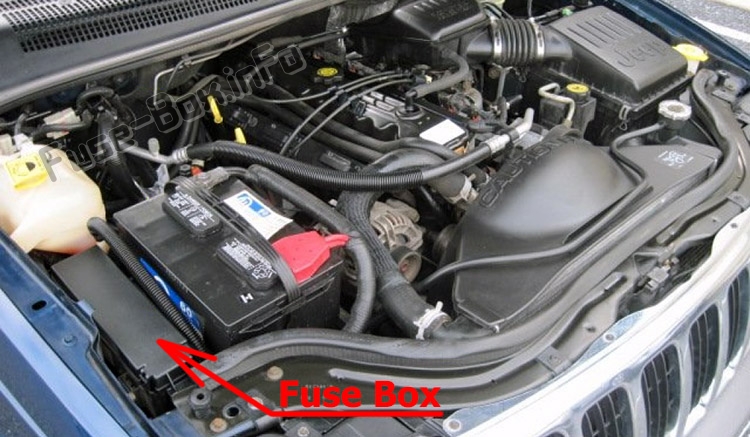
Fuse box diagram
Assignment of the fuses and relay in Power Distribution Center
| № | Amp Rating | Description |
|---|---|---|
| 1 | 40 | Blower Motor (MTC), Blower Motor Controller (AZC) |
| 2 | 40 | Rear Window Defogger Relay (Rear Window Defogger, Fuse (Passenger Compartment): “11”), Cigar Lighter Relay (Trailer Tow Circuit Breaker, Fuse (Passenger Compartment): “26”) |
| 3 | 50 | High Beam Relay (Fuse (Passenger Compartment): “3”, “16”), Low Beam Relay (Fuse (Passenger Compartment): “14”, “15”) or Low Beam / Daytime Running Lamp Relay (Fuse (Passenger Compartment): “14”, “15”), Fuse (Passenger Compartment): “4”, “5”, “6”, “11”, “17” |
| 4 | 40 | ABS |
| 5 | 30 | Gasoline: Transmission Control Relay, Transmission Control Module (4.7L), Transmission Solenoid (4.0L), Transmission Solenoid/TRS Assembly (4.7L) |
| 6 | 30 or 50 | Gasoline (30A): Automatic Shut Down Relay (Ignition Coils, Capacitor, Fuse (Engine Compartment): “16”, “26”);
Diesel (50A): Glow Glug Relay No.1 (Glow Plug: No.1, 3, 5) |
| 7 | 50 | Fuse (Passenger Compartment): “23”, “24”, “25”, “27”, “C2” |
| 8 | 40 | Starter Relay, Ignition Switch (Fuse (Passenger Compartment): “12”, “21”, “22”, “28”, “29”, “30”, “32”, “C1”) |
| 9 | 20 | Diesel: Fuel Heater Relay |
| 10 | 40 | Radiator Fan Relay |
| 11 | 50 | Diesel: Glow Glug Relay No.2 (Glow Plug: No.2, 4) |
| 12 | 50 | Driver/Passenger Door Module, Fuse (Passenger Compartment): “18” |
| 13 | 30 | Diesel: Automatic Shut Down Relay (Engine Control Module, Powertrain Control Module, Fuse (Engine Compartment): “16”, “26”) |
| 14 | 40 | Ignition Switch (Fuse (Passenger Compartment): “19”, “20”, “31”, “33”) |
| 15 | 50 | Fuse (Passenger Compartment): “5”, “7”, “8”, “9” |
| 16 | 10 or 15 | Gasoline (2001) (15A): Oxygen Sensors, Oxygen Sensor Downstream Relay;
Gasoline (1999-2000) (10A): Oxygen Sensors; Diesel (10A): Air Conditioner Compressor Clutch Relay, Glow Plug Relay No.1, Glow Plug Relay No.2, EGR Solenoid |
| 17 | 20 | Gasoline (1999-2000): Oxygen Sensor Downstream Relay, Oxygen Sensor Upstream Relay |
| 18 | 15 | Horn Relay |
| 19 | 10 | Gasoline: Powertrain Control Module |
| 20 | – | Not Used |
| 21 | 15 | Air Conditioner Compressor Clutch Relay |
| 22 | – | Not Used |
| 23 | – | Not Used |
| 24 | 15 or 20 | Gasoline: Fuel Pump Relay;
Diesel: Powertrain Control Module, Transmission Control Relay |
| 25 | 20 | ABS |
| 26 | 15 | Gasoline: Fuel Injectors;
Diesel: Fuel Injection Pump |
| 27 | – | Not Used |
| 28 | 15 | 4.0L: Transmission Solenoid |
| Relay | ||
| R1 | Gasoline: Fuel Pump;
Diesel: Wiper (On/Off) |
|
| R2 | Gasoline: Starter;
Diesel: Wiper (High/Low) |
|
| R3 | Gasoline: Transmission Control;
Diesel: Fuel Heater |
|
| R4 | Gasoline: Wiper (On/Off);
Diesel: Transmission Control |
|
| R5 | Gasoline: Wiper (High/Low);
Diesel: Starter |
|
| R6 | Gasoline: Oxygen Sensor Downstream | |
| R7 | Gasoline: Oxygen Sensor Upstream | |
| R8 | Air Conditioner Compressor Clutch | |
| R9 | Horn | |
| R10 | Automatic Shut Down | |
| R11 | Diesel: Glow Plug (No.1) | |
| R12 | Diesel: Glow Plug (No.2) |


