

Fuse Layout Cadillac ELR 2014-2016
Contents
Cigar lighter (power outlet) fuses in the Cadillac ELR are the fuse №F1 (Power Outlet/Cigarette Lighter – Top of IP Storage Bin) and fuse №F15 (Inside Console Bin Power Outlet) in the Left side Instrument panel fuse box.
Table of Contents
Passenger compartment
Passenger compartment
Fuse Box Location
There are two fuse boxes that are located on both sides of the instrument panel, behind covers.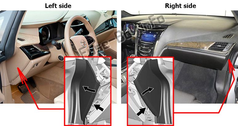
Fuse box diagram (Left side)
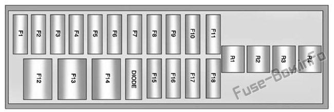
Assignment of the fuses and relays in the instrument panel (Left side)
| № | Ampere rating [A] | Description |
|---|---|---|
| F1 | 20 | Power Outlet/Cigarette Lighter – Top of IP Storage Bin |
| F2 | 15 | Infotainment (HMI, CD) |
| F3 | 10 | Instrument Cluster |
| F4 | 10 | Infotainment Display, Steering Wheel Control Switches |
| F5 | 10 | Heating, Ventilation, & Air Conditioning |
| F6 | 10 | Airbag (Sensing Diagnostic Module/Passenger Sensing Module) |
| F7 | 15 | Data Link Connector, Left (Primary) |
| F8 | 10 | Column Lock |
| F9 | 10 | OnStar |
| F10 | 15 | Body Control Module 1/Body Control Module Electronics/Keyless Entry/Power Moding/Center High Mounted Stoplamp/License Plate Lamps/Left Daytime Running Lamp/Left Parking Lamps/Trunk Release Relay Control/Washer Pump Relay Control/Switch Indicator Lights |
| F11 | 15 | Body Control Module 4/Left Headlamp |
| F12 | — | Empty |
| F13 | — | Empty |
| F14 | — | Empty |
| F15 | 20 | Power Outlet (Inside Console Bin) |
| F16 | 5 | Wireless Charger |
| F17 | — | Empty |
| F18 | — | Empty |
| Diode | Empty | |
| Relays | ||
| R1 | Retained Accessory Power Relay for Power Outlets | |
| R2 | Empty | |
| R3 | Empty | |
| R4 | Empty |
Fuse box diagram (Right side)
Assignment of the fuses and relays in the instrument panel (Right side)
| № | Ampere rating | Description |
|---|---|---|
| F1 | 2 | Steering Wheel Switch |
| F2 | 10 | Auto Headlamp Leveling |
| F3 | 10 | Motorized Cup Holder |
| F4 | 15 | Body Control Module 3/Right Headlamp |
| F5 | 7.5 | Body Control Module 2/ Body Control Module Electronics/ Trunk Lamp/ Right Daytime Running Lamp/Shifter Lock/Switch Backlighting |
| F6 | 15 | Tilt/Telescope Column |
| F7 | 7.5 | Body Control Module 6/ Map Lights/ Courtesy Lights/ Back-up Lamp |
| F8 | 15 | Body Control Module 7/Left Front Turn Signal/Right Rear Stop and Turn Signal Lamp |
| F9 | — | Empty |
| F10 | 15 | Data Link Connector, Right (Secondary) |
| F11 | 7.5 | Universal Garage Door Opener, Rain Sensor, Front Camera |
| F12 | 30 | Blower Motor |
| F13 | — | Empty |
| F14 | — | Empty |
| F15 | — | Empty |
| F16 | 10 | Glove Box |
| F17 | — | Empty |
| F18 | — | Empty |
| DIODE | Empty | |
| Relays | ||
| R1 | Empty | |
| R2 | Glove Box Door | |
| R3 | Empty | |
| R4 | Empty |
Engine compartment
Engine compartment
Fuse Box Location
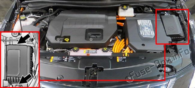
Fuse box diagram
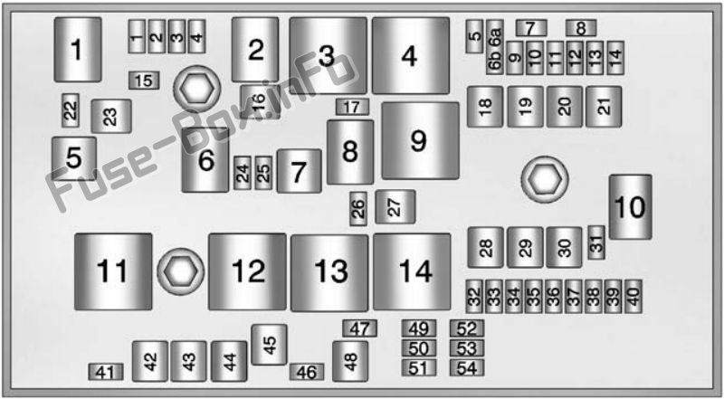
Assignment of the fuses and relays in the Engine compartment
| № | Ampere rating [A] | Description |
|---|---|---|
| Mini Fuses | ||
| 1 | 15 | Engine Control Module – Switched Power |
| 2 | 7.5 | Emissions |
| 3 | – | Not Used |
| 4 | 15 | Ignition Coils/Injectors |
| 5 | 10 | Column Lock |
| 6a | – | Empty |
| 6b | – | Empty |
| 7 | – | Empty |
| 8 | – | Empty |
| 9 | 7.5 | Heated Mirrors |
| 10 | 5 | Air Conditioning Control Module |
| 11 | 7.5 | Traction Power Inverter Module – Battery |
| 12 | – | Not Used |
| 13 | 10 | Cabin Heater Pump and Valve |
| 14 | – | Not Used |
| 15 | 15 | Traction Power Inverter Module and Transmission Control Module – Battery |
| 17 | 5 | Engine Control Module – Battery |
| 22 | 10 | Left High-Beam Headlamp |
| 24 | – | Empty |
| 25 | – | Empty |
| 26 | – | Not Used |
| 31 | 5 | Adaptive Cruise Control/Auto Headlamp |
| 32 | 5 | Vehicle Integration Control Module |
| 33 | 10 | Run/Crank for Heated Steering Wheel |
| 34 | 10 | Vehicle Integration Control Module – Battery |
| 35 | – | Not Used |
| 36 | 10 | Power Electronics Coolant Pump |
| 37 | 5 | Cabin Heater Control Module |
| 38 | 10 | Rechargeable Energy Storage System (High Voltage Battery) Coolant Pump |
| 39 | 10 | Rechargeable Energy Storage System (High Voltage Battery) Control Module |
| 40 | 10 | Front Windshield Washer |
| 41 | 10 | Right High-Beam Headlamp |
| 46 | – | Empty |
| 47 | – | Empty |
| 49 | – | Empty |
| 50 | 10 | Run/Crank – Rear Vision Camera, Accessory Power Module |
| 51 | 7.5 | Run/Crank for ABS, Aero Shutter, VITM |
| 52 | 5 | Engine Control Module/Transmission Control Module – Run/Crank |
| 53 | 7.5 | Traction Power Inverter Module – Run/Crank |
| 54 | 7.5 | Run/Crank – Fuel System Control Module, Air Conditioning Control Module, On Board Charger, Instrument Cluster, Automatic Occupant Sensing, Mirrors |
| J-Case Fuses | ||
| 16 | 20 | AIR Solenoid (PZEV Only) |
| 18 | 30 | Rear Defogger Lower Grid |
| 19 | 30 | Power Window – Front |
| 20 | – | Empty |
| 21 | 30 | Antilock Brake System Electronic Control Unit |
| 23 | – | Empty |
| 27 | 40 | AIR Pump (PZEV Only) |
| 28 | – | Empty |
| 29 | 30 | Front Wipers |
| 30 | 60 | Antilock Brake System Motor |
| 42 | 30 | Cooling Fan – Right |
| 43 | 30 | Front Wipers |
| 44 | 40 | Charger |
| 45 | – | Empty |
| 48 | 30 | Cooling Fan – Left |
| Mini Relays | ||
| 3 | Powertrain | |
| 4 | Heated Mirrors | |
| 7 | Empty | |
| 9 | AIR Pump (PZEV Only) | |
| 11 | Empty | |
| 12 | Empty | |
| 13 | Empty | |
| 14 | Run/Cran | |
| Micro Relays | ||
| 1 | Empty | |
| 2 | AIR Solenoid (PZEV Only) | |
| 6 | Empty | |
| 8 | Empty | |
| 10 | Empty | |
| Ultra Micro Relays | ||
| 5 | Empty |
Fuse Boxes in the luggage compartment
Fuse Boxes in the luggage compartment
Fuse Box Location
They are located in the left side of the trunk, behind the cover.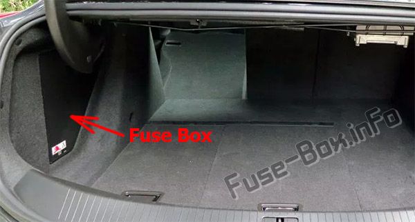
Fuse box diagram (Fuse Box №1)
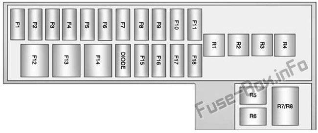
Assignment of the fuses and relays in the Luggage compartment box №1
| № | Ampere rating [A] | Description |
|---|---|---|
| F1 | — | Empty |
| F2 | 15 | Fuel System Control Module |
| F3 | 5 | Passive Entry/Passive Start |
| F4 | 15 | Heated Seats |
| F5 | 2 | Regulated Voltage Control, Current Sensor |
| F6 | 10 | Fuel (Diurnal Valve and Evap. Leak Check Module) |
| F7 | 15 | Accessory Power Module Cooling Fan |
| F8 | 30 | Amplifier |
| F9 | — | Empty |
| F10 | 5 | Regulated Voltage Control/Ultrasonic Front and Rear Parking Assist, Side Blind Zone |
| F11 | 15 | Horn |
| F12 | — | Empty |
| F13 | 30 | Electric Parking Brake |
| F14 | 30 | Rear Defog (Upper Grid) |
| F15 | — | Empty |
| F16 | 10 | Trunk Release |
| F17 | — | Empty |
| F18 | — | Empty |
| DIODE | Empty | |
| Relays | ||
| R1 | Rear Defog (Upper Grid) | |
| R2 | Trunk Release | |
| R3 | Empty | |
| R4 | Empty | |
| R5 | Empty | |
| R6 | Empty | |
| R7/R8 | Horn |
Fuse box diagram (Fuse Box №2)
Assignment of the fuses and relays in the Luggage compartment box №2
| № | Ampere rating [A] | Description |
|---|---|---|
| F1 | — | Empty |
| F2 | 15 | Radio |
| F3 | 10 | Pedestrian Protection |
| F4 | 10 | CDC |
| F5 | 10 | Memory Seat Module |
| F6 | — | Empty |
| F7 | 10 | Mirror/Window/Seat Switch |
| F8 | 20 | Passive Entry/Passive Start 2 |
| F9 | 15 | Heated Seat 2 |
| F10 | — | Empty |
| F11 | — | Empty |
| F12 | 30 | Driver Power Seat |
| F13 | 30 | Passenger Power Seat |
| F14 | — | Empty |
| F15 | — | Empty |
| F16 | — | Empty |
| F17 | — | Empty |
| F18 | — | Empty |
| DIODE | Empty | |
| Relays | ||
| R1 | Empty | |
| R2 | Empty | |
| R3 | Empty | |
| R4 | Empty |


